

Image processing apparatus and image processing program product
a technology which is applied in the field of image processing apparatus and image processing program product, can solve the problems of requiring a lot of time and effort to observe the series of observation images of a doctor, a nurse, or the lik
- Summary
- Abstract
- Description
- Claims
- Application Information
AI Technical Summary
Problems solved by technology
Method used
Image

Examples
first embodiment
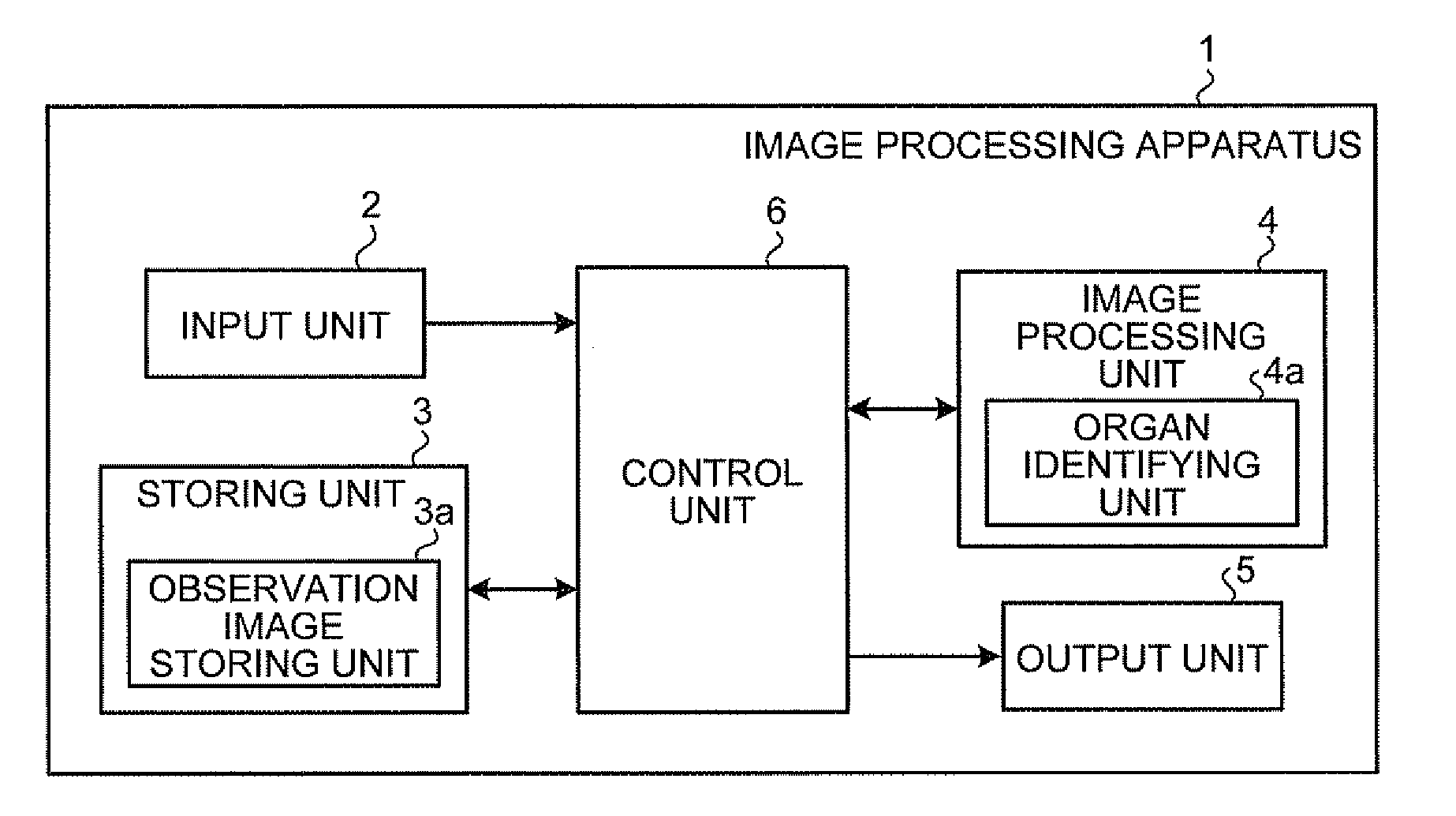
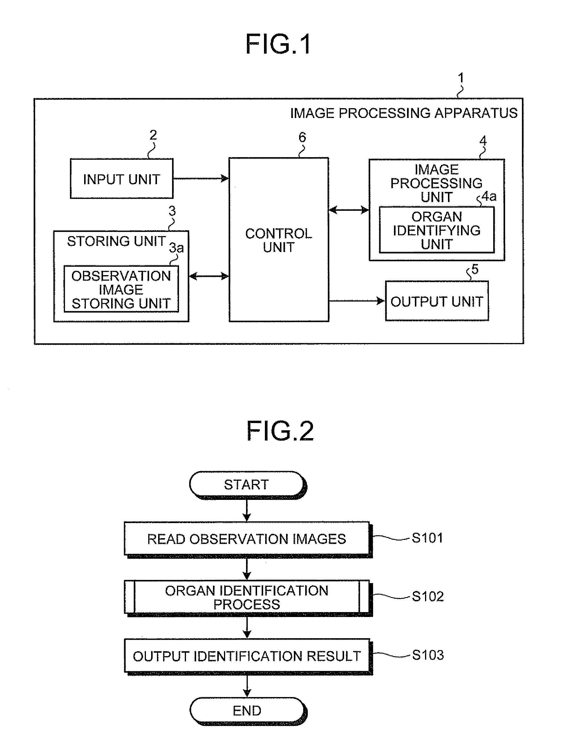
[0022]First, an image processing apparatus according to the first embodiment of the present invention will be explained. FIG. 1 is a block diagram illustrating the main configuration of an image processing apparatus 1 according to the first embodiment. As illustrated in FIG. 1, the image processing apparatus 1 includes an input unit 2, a storing unit 3, an output unit 5, an image processing unit 4, and a control unit 6. The input unit 2 receives various types of information including an image, the storing unit 3 stores therein the same, and the output unit 5 outputs the same. The image processing unit 4 processes an image stored in the storing unit 3. The control unit 6 is electrically connected to the units and controls a process and an operation of each unit.
[0023]The input unit 2 can be a data communication interface. The data communication interface inputs image data of a series of observation images to be processed into the control unit 6. In the first embodiment, the image dat...
second embodiment
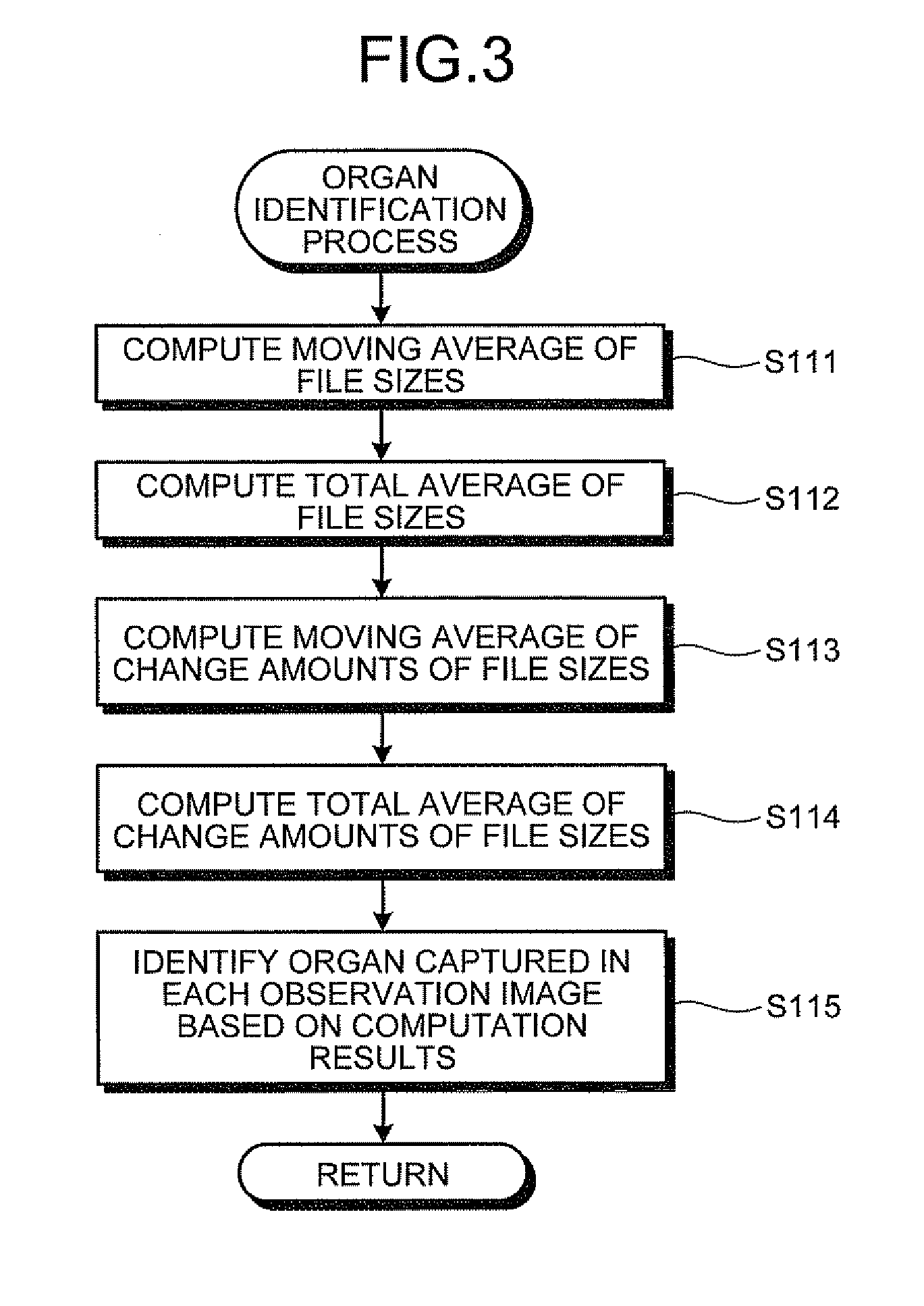
[0049]Next, the image processing apparatus according to the second embodiment of the present invention will be explained. In the first embodiment as described above, the organ identifying unit 4a identifies an organ captured on each observation image on the basis of file sizes of compressed image data of observation images and change amounts thereof. In the second embodiment, the organ identifying unit 4a identifies an organ on the basis of DCT coefficients computed at the time of decompression of compressed image data and change amounts thereof. The image processing apparatus according to the second embodiment has the same configuration as that of the image processing apparatus 1, and the organ identifying unit 4a performs an organ identification process of Step S102 on the basis of a DCT coefficient instead of a file size.
[0050]An esophagus or a stomach usually has a mucous membrane surface that has a little unevenness and is flat as compared to a small intestine. On the other han...
third embodiment
[0067]Next, an image processing apparatus according to the third embodiment of the present invention will be explained. In the second embodiment as described above, the organ identifying unit 4a identifies an organ captured on each observation image on the basis of representative DCT coefficients of an observation image and a change amount of the representative DCT coefficients. In the third embodiment, the organ identifying unit calculates a feature vector based on a plurality of DCT coefficients for each observation image and identifies an organ on the basis of the feature vector.
[0068]FIG. 7 is a block diagram illustrating the main configuration of an image processing apparatus 10 according to the third embodiment. As illustrated in FIG. 7, the image processing apparatus 10 includes a storing unit 13, an image processing unit 14, and a control unit 16 instead of the storing unit 3, the image processing unit 4, and the control unit 6, respectively, based on the configuration of th...
PUM
 Abstract
Description
Claims
Application Information