Cooperative target capture locking device

A locking device and cooperation target technology, applied in the field of robots, can solve the problems of large impact force, poor capture reliability, small capture tolerance, etc., and achieve the effect of small impact force, reasonable design, and reduced collision

Active Publication Date: 2013-09-25
HARBIN INST OF TECH
View PDF5 Cites 24 Cited by
  • Summary
  • Abstract
  • Description
  • Claims
  • Application Information

AI Technical Summary

Problems solved by technology

[0003] The purpose of the present invention is to solve the problems of small capture tolerance, poor capture reliability and large impact force in the capture process of the existing space manipulator end effector in the capture process, and then provide a cooperative target capture Locking device

Method used


Image

  • Cooperative target capture locking device
  • Cooperative target capture locking device
  • Cooperative target capture locking device

Examples


specific Embodiment approach 1

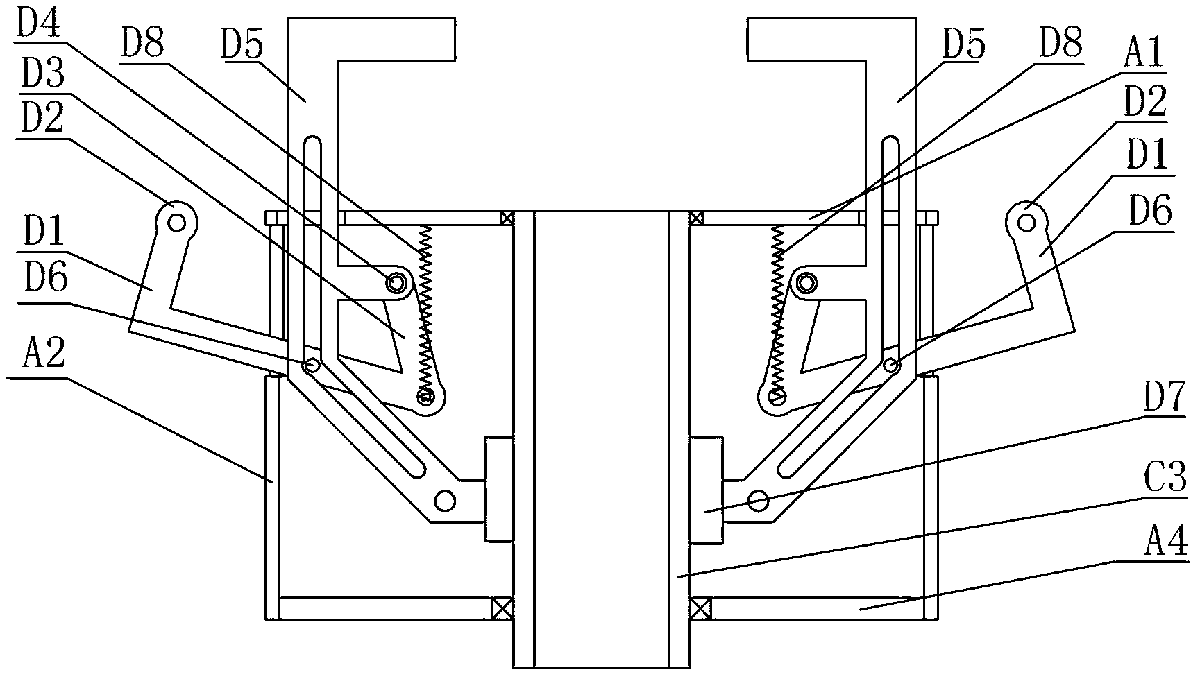
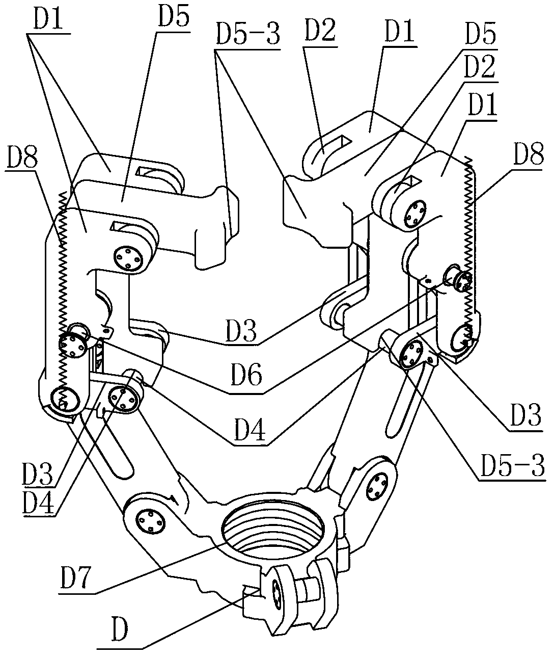
[0007] Specific implementation mode one: combine Figure 1-Figure 3 To illustrate this embodiment, a cooperation target capturing and locking device of this embodiment includes a cover plate A1, a supporting shell A2, a bottom plate A4, a lead screw C3, a disc D7 and three sets of capturing and locking fingers;

[0008] The supporting shell A2 is a cylindrical shell, the cover plate A1 is connected to the upper end of the supporting shell A2, the bottom plate A4 is installed on the lower end of the supporting shell A2, the lead screw C3 is arranged along the axis of the supporting shell A2, and the lead screw C3 The upper end of the screw is connected to the cover plate A1 in rotation, and the lower end of the lead screw C3 is connected to the bottom plate A4 in rotation. Each group of capturing and locking fingers includes a capturing claw D5, a linkage shaft D4, a guide column D6, two locking claws D1, and two locking claws. Wheel D2, two connecting rods D3 and two springs D...

specific Embodiment approach 2

[0009] Specific implementation mode two: combination figure 1 The present embodiment will be described, and the screw C3 described in the present embodiment is a ball screw. With such settings, the performance is reliable and stable. Others are the same as in the first embodiment.

specific Embodiment approach 3

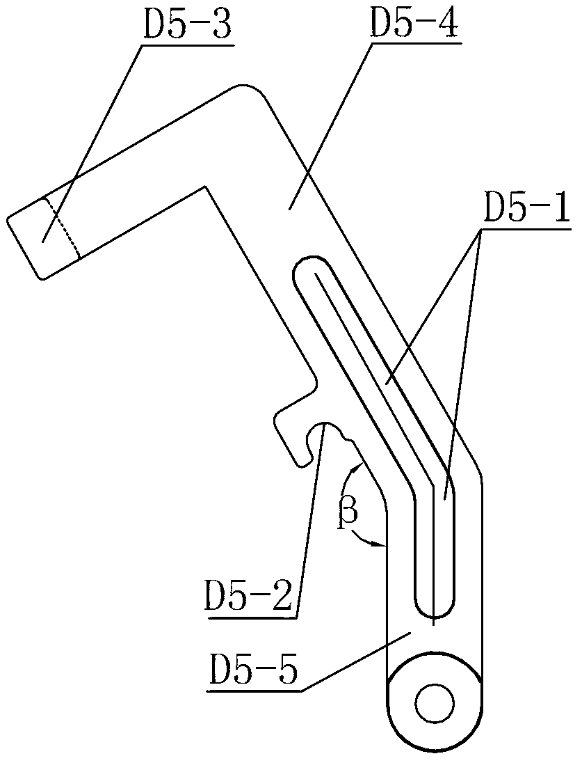
[0010] Specific implementation mode three: combination figure 2 and image 3 To describe this embodiment, the guide hole D5-1 in this embodiment is arched. With such arrangement, the catch claw and the locking claw can be well opened and closed, and the pre-tightening and locking are well realized. Others are the same as in the first or second embodiment.


PUM


Abstract

The invention provides a cooperative target capture locking device, and relates to a three-finger capture locking device. The cooperative target capture locking device aims to resolve the problems that an existing space mechanical arm tail-end actuator has small capture allowance and poor capture reliability in a capture process, and large impact force occurs in the capture process. The cooperative target capture locking device comprises a covering board, a supporting shell, a bottom board, a screw, a disc and three sets of capture locking fingers, wherein the covering board is connected to the upper end of the supporting shell, the bottom board is arranged at the lower end of the supporting shell, and the screw is arranged along the axis of the supporting shell. Each set of capture finger comprises a capture claw, a linkage shaft, a guide column, two locking claws, two locking wheels, two connection rods and two springs, the three sets of capture fingers are evenly distributed on the outer circular wall of the disc, a connection section is rotationally connected with the disc, the two ends of the guide column are connected with the supporting shell, and the short edge of each locking claw is provided with each locking wheel. The cooperative target capture locking device is used for cooperative target capture locking on the space mechanical arm tail-end actuator.

Description

technical field [0001] The invention relates to a three-finger capturing and locking device, in particular to a cooperative target capturing and locking device for a space manipulator end effector, belonging to the technical field of robots. Background technique [0002] At present, the relatively successful design schemes for the end effector of the space manipulator mainly include the Orbital Express in the United States and the ERA manipulator arm of the European Space Agency. The capture and locking devices of the two end effectors both adopt a three-finger structure, and both belong to the technical scheme of envelope capture. Among them, the U.S. track express program lacks a locking mechanism, and because it uses a four-bar linkage, the reliability is poor, and there is a large impact force during the capture process. The capture device of the ESA robotic arm ERA has a small capture tolerance. Contents of the invention [0003] The purpose of the present invention...

Claims


Application Information

Patent Timeline
Patent Type & Authority Applications(China)
IPC IPC(8): B25J15/10
Inventor 刘宏曹宝石孙奎谢宗武朱映远韩锋
Owner HARBIN INST OF TECH
Why Eureka
Try Eureka