
Automatic fastener driving system, apparatus and method

Active Publication Date: 2016-04-07
HONDA MOTOR CO LTD
View PDF27 Cites 7 Cited by
  • Summary
  • Abstract
  • Description
  • Claims
  • Application Information

AI Technical Summary

Benefits of technology

The patent text describes an automatic fastener driving system and method that can quickly and efficiently install fasteners on a work piece without the need for manual labor. The system includes a fastener supplying device, a transfer device, and a fastener driving apparatus. The fastener driving apparatus has a receiver for holding the fastener, an alignment device for aligning the fastener with the work piece, and a torqueing device for applying powered torque to the fastener to install it. The resolution of the technical problem addressed by this invention is the need for a faster, more efficient way to install fasteners on work pieces.

Problems solved by technology

Conventionally known tools of this type are usually large and heavy, also expensive to install and operate.
An additional drawback of these types of known tools is that insertion of the threaded bolt into the tool in the thread-first orientation can result in damage to the threaded bolt (e.g., to the threads of the threaded bolt).

Method used


Image

  • Automatic fastener driving system, apparatus and method
  • Automatic fastener driving system, apparatus and method
  • Automatic fastener driving system, apparatus and method

Examples


Embodiment Construction

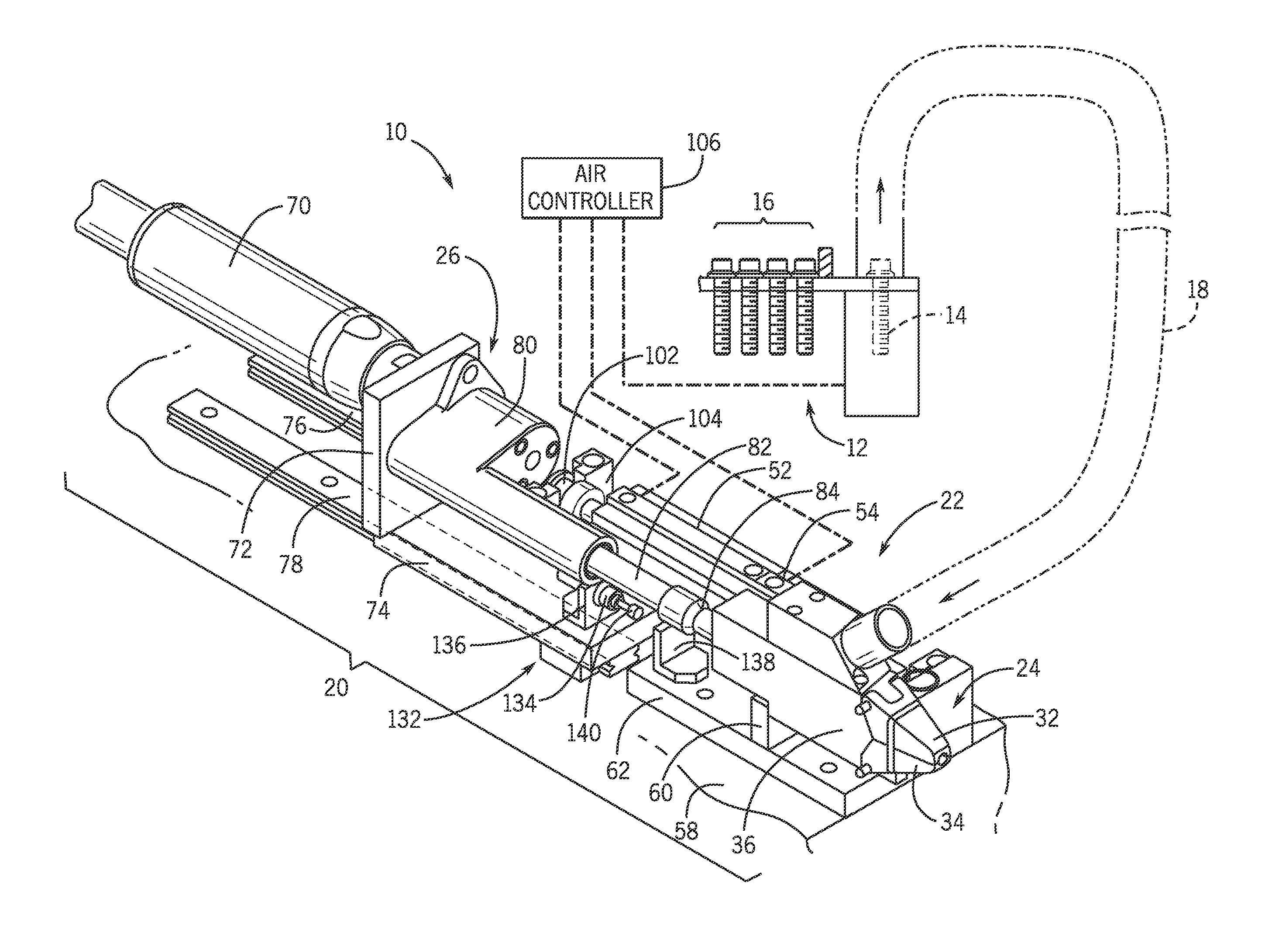
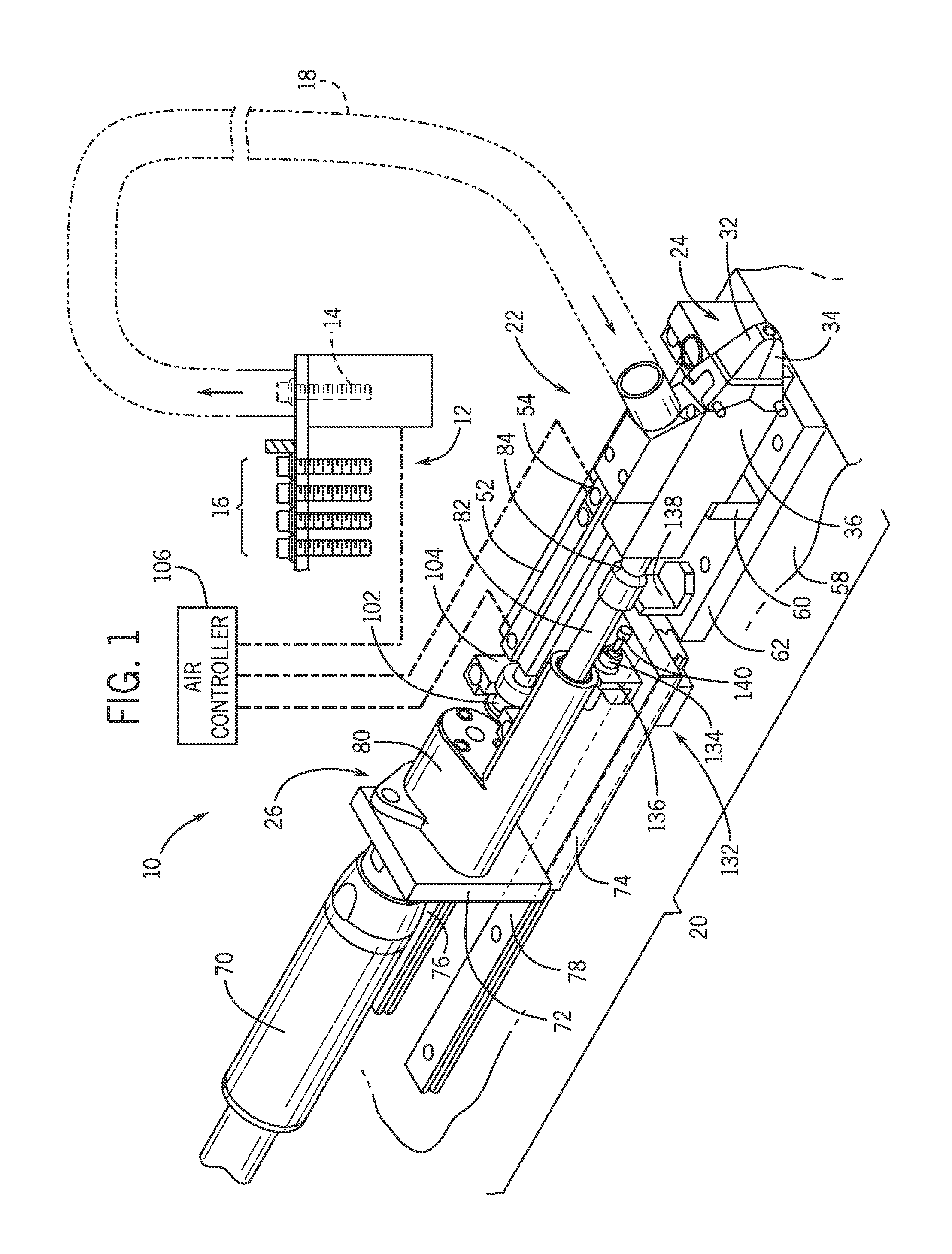
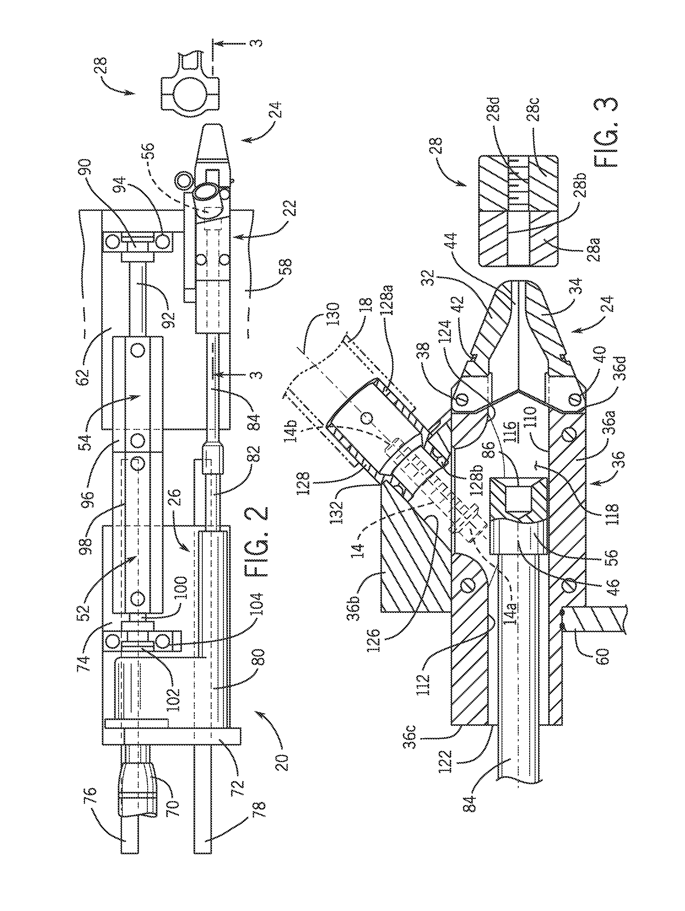
[0017]With reference now to the figures wherein the showings are for purposes of illustrating one or more exemplary embodiments and not for purposes of limiting the same, FIG. 1 illustrates an automatic fastener driving system 10 according to an exemplary embodiment and generally indicated by reference numeral 10. The system 10 can include a fastener supplying device 12 for supplying a fastener 14 from a plurality of fasteners 16 in a head first orientation and is connected to a transfer device 18 that is operatively connected to the fastener supplying device 12 for transferring the fastener 14. The system 10 includes a fastener driving apparatus 20. The fastener driving apparatus 20 may be operatively connected to the transfer device 18 for receipt of the fastener 14 in the head first orientation. The transfer device 18 in the illustrated embodiment is or includes a transfer tube through which the fastener 14 is transferred via pneumatic force (e.g., in the head first orientation)....


PUM

PropertyMeasurementUnit
Angleaaaaaaaaaa
Lengthaaaaaaaaaa
Forceaaaaaaaaaa

Abstract

A fastener driving system, apparatus and method includes a receiver into which the fastener is deposited and a torqueing device extendable into the receiver for applying powered torque to the fastener to install the fastener into the associated work piece.

Description

BACKGROUND[0001]Many conventional automatic fastener devices are known. In most conventionally known tools, a threaded bolt is fed into the tool in a thread-first orientation. The tool is typically oriented into a vertical direction so that the threaded bolt drops into jaws of the tool which hold the threaded bolt for engagement with a work piece. Conventionally known tools of this type are usually large and heavy, also expensive to install and operate. An additional drawback of these types of known tools is that insertion of the threaded bolt into the tool in the thread-first orientation can result in damage to the threaded bolt (e.g., to the threads of the threaded bolt).BRIEF DESCRIPTION[0002]According to one aspect, an automatic fastener driving system includes a fastener supplying device for supplying a fastener in a head first orientation, a transfer device operatively connected to the fastener supplying device for transferring the fastener, and a fastener driving apparatus op...

Claims


Application Information

Patent Timeline
IPC IPC(8): B23P19/00B23P19/06
CPCB23P19/06B23P19/005B23P19/002B23P19/003B23P19/006B25B23/06B25B23/103Y10T29/49881Y10T29/49947Y10T29/49963
Inventor BEATY, ERIC L.
Owner HONDA MOTOR CO LTD
Learn More