Lane boundary line information acquiring device

a technology of information acquisition and lane boundary line, which is applied in the direction of image enhancement, instruments, transportation and packaging, etc., can solve the problems of incorrect assist control of the own and difficulty in correctly detecting the lane boundary lin

Active Publication Date: 2016-04-07
DENSO CORP
View PDF4 Cites 10 Cited by
  • Summary
  • Abstract
  • Description
  • Claims
  • Application Information

AI Technical Summary

Benefits of technology

The patent describes a device that can detect the borders of lanes on a road and use them to control the vehicle's behavior. This device can work even when the lanes are not always visible. It uses information about the vehicle's position and the likelihood of finding a lane boundary line to make corrective decisions. This means that the device can help the driver keep within the lane, avoiding accidents or other driving mistakes.

Problems solved by technology

However, there is a possible case of it being difficult to correctly detect a lane boundary line from the images captured by the in-vehicle camera due to a road-surface condition, etc.
If a control device of the own vehicle executes the lane keeping control on the basis of incorrect lane boundary line information, there is a possible case of performing an incorrect assist control of the own vehicle.

Method used


Image

  • Lane boundary line information acquiring device
  • Lane boundary line information acquiring device
  • Lane boundary line information acquiring device

Examples


first exemplary embodiment

[0023]A description will be given of a lane boundary line information acquiring device 1 according to a first exemplary embodiment with reference to FIG. 1 to FIG. 4.

1. Structure of the Lane Boundary Line Information Acquiring Device 1

[0024]A description will now be given of the lane boundary line information acquiring device 1 according to the first exemplary embodiment with reference to FIG. 1.

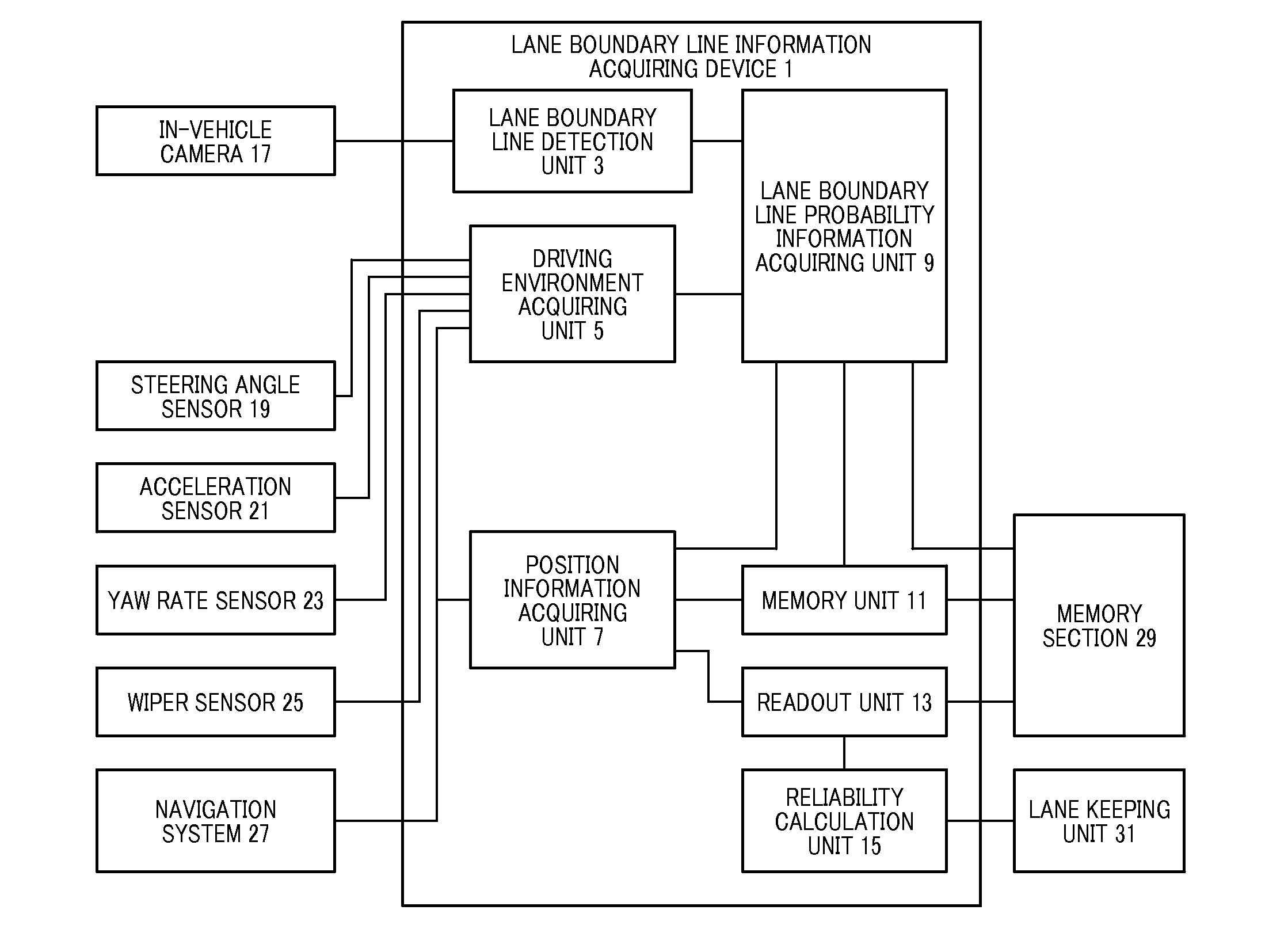
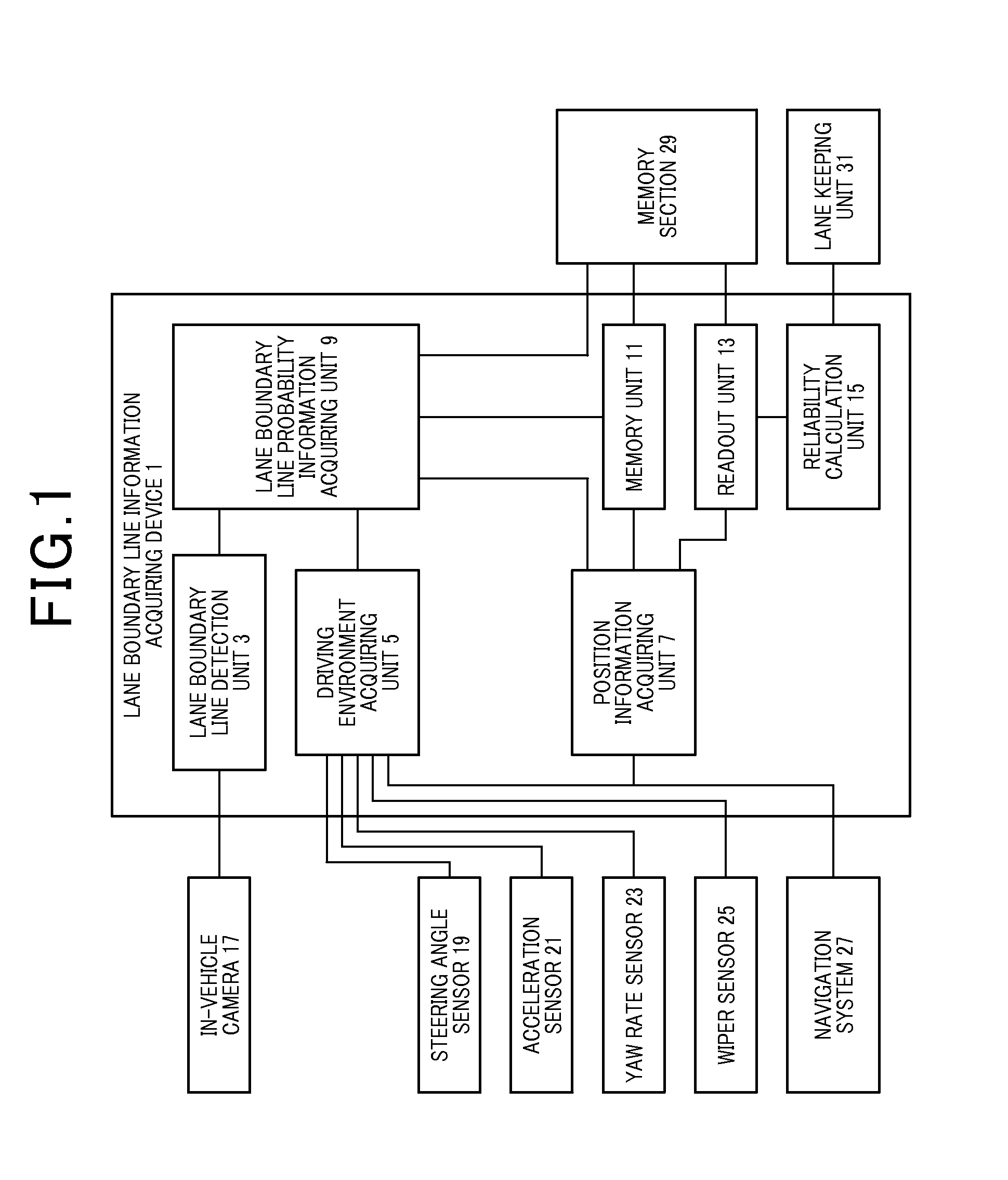
[0025]FIG. 1 is a block diagram showing a structure of the lane boundary line information acquiring device 1 according to the first exemplary embodiment. The lane boundary line information acquiring device 1 is mounted to an own vehicle.

[0026]The lane boundary line information acquiring device 1 consists of a computer equipped with a central processing unit (CPU), a random access memory (RAM), a read only memory (ROM), etc. Programs are stored in advance into the memory such as the ROM. The lane boundary line information acquiring device 1 is equipped with functional units, i.e. a lane bound...

second exemplary embodiment

[0080]A description will be given of the lane boundary line information acquiring device 1 according to a second exemplary embodiment with reference to FIG. 5.

1. Structure of the Lane Boundary Line Information Acquiring Device 1 according to the second exemplary embodiment

[0081]The lane boundary line information acquiring device 1 according to the second exemplary embodiment has the same structure as the lane boundary line information acquiring device 1 according to the first exemplary embodiment. Accordingly, the explanation of the structure of the lane boundary line information acquiring device 1 according to the second exemplary embodiment is omitted here.

2. Lane Boundary Line Probability Information Storing Process Performed by the Lane Boundary Line Information Acquiring Device 1 According to the Second Exemplary Embodiment

[0082]FIG. 5 is a flow chart showing the lane boundary line probability information storing process executed by the lane boundary line information acquiring ...

third exemplary embodiment

[0090]A description will be given of the lane boundary line information acquiring device 1 according to a third exemplary embodiment with reference to FIG. 6.

[0091]FIG. 6 is a flow chart showing the lane boundary line probability information storing process executed by the lane boundary line information acquiring device according to the third exemplary embodiment.

1. Structure of the Lane Boundary Line Information Acquiring Device 1 According to the Third Exemplary Embodiment

[0092]The lane boundary line information acquiring device 1 according to the third exemplary embodiment has the same structure of the lane boundary line information acquiring device 1 according to the first exemplary embodiment. Accordingly, the explanation of the structure of the lane boundary line information acquiring device 1 according to the third exemplary embodiment is omitted here.

2. Lane Boundary Line Probability Information Storing Process Performed by the Lane Boundary Line Information Acquiring Device...


PUM


Abstract

In a lane boundary line information acquiring device, a detection unit detects lane boundary lines. A driving environment acquiring unit acquires a driving environment. A probability information acquiring unit acquires probability information containing a probability of presence of a lane boundary line, etc. based on the detected lane boundary lines and the acquired driving environment. A position information acquiring unit acquires position information of the own vehicle. A memory unit associates the probability information with the position information of the own vehicle. Where the position information is acquired by the position information acquiring unit at a time when the probability information acquiring unit acquires the probability information, and stores the probability information associated with the position information into the memory unit. A readout unit reads out the probability information associated with the position information at a location in front of the own vehicle.

Description

CROSS-REFERENCE TO RELATED APPLICATION[0001]This application is related to and claims priority from Japanese Patent Application No. 2014-203730 filed on Oct. 2, 2014, the contents of which are hereby incorporated by reference.BACKGROUND OF THE INVENTION[0002]1. Field of the Invention[0003]The present invention relates to lane boundary line information acquiring devices capable of correctly recognizing lane boundary lines on a roadway on which an own vehicle drives and supporting correct driving assist such as a lane keeping control and a lane departure warning even if a visibility of lane boundary lines is not reduced.[0004]2. Description of the Related Art[0005]Recently, there has been developed and known a technology for detecting lane boundary lines on a roadway on which an own vehicle drives on the basis of images around the own vehicle acquired by an in-vehicle camera. For example, there are white lines, Botts' dots, cat's eyes, etc. as the lane boundary lines. Such cat's eyes ...

Claims


Application Information

Patent Timeline
IPC IPC(8): G06K9/00G06K9/46G06K9/52G06T7/00G06V10/44G06V10/764
CPCG06K9/00798G06T7/004G06T2207/30256G06K9/4604G06K9/52G06T7/0085B60W30/12B60W2540/18B60W2520/105B60W2520/14B60W40/06B60W2555/20B60W2556/50B60W2556/20G06V20/588G06V10/44G06V10/764B60W2420/403G06F18/2415
Inventor OKADA, MASAYAKAWASAKI, NAOKIUEDA, YUSUKEOOOKA, MASAOFUKUDA, SHOTARO
Owner DENSO CORP
Why Eureka
Try Eureka