
Electrical Interruption Apparatus With Wear Indicator

Active Publication Date: 2016-04-07
EATON INTELLIGENT POWER LIMITED
View PDF11 Cites 3 Cited by
  • Summary
  • Abstract
  • Description
  • Claims
  • Application Information

AI Technical Summary

Benefits of technology

[0007]Accordingly, an aspect of the disclosed and claimed concept is to provide an improved electrical interruption apparatus having a wear indicato

Problems solved by technology

It is understood, however, that electrical arcing between the contacts can result in vaporization of the material of the contacts and resultant wear of the contacts.
Since such electrical interruption devices typically include a mechanism that is spring loaded and that applies a compressive force to maintain the contacts in their closed position, a loss of the material of the contacts due to wear can require the contacts to move a relatively greater distance in order to beco

Method used


Image

  • Electrical Interruption Apparatus With Wear Indicator
  • Electrical Interruption Apparatus With Wear Indicator
  • Electrical Interruption Apparatus With Wear Indicator

Examples


Example

[0018]Similar numerals refer to similar parts throughout the specification.

DESCRIPTION

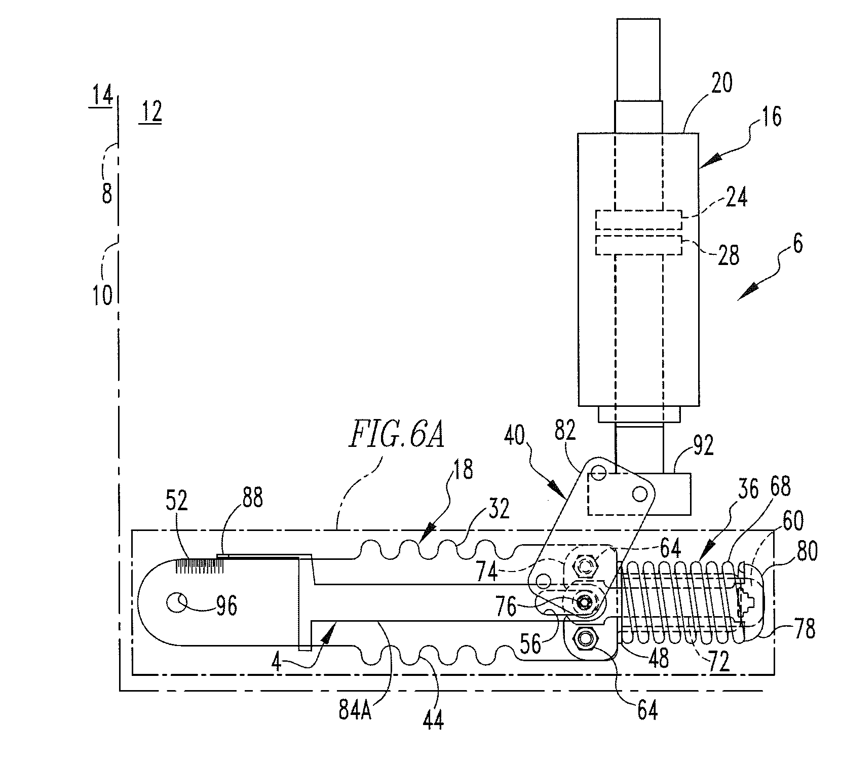
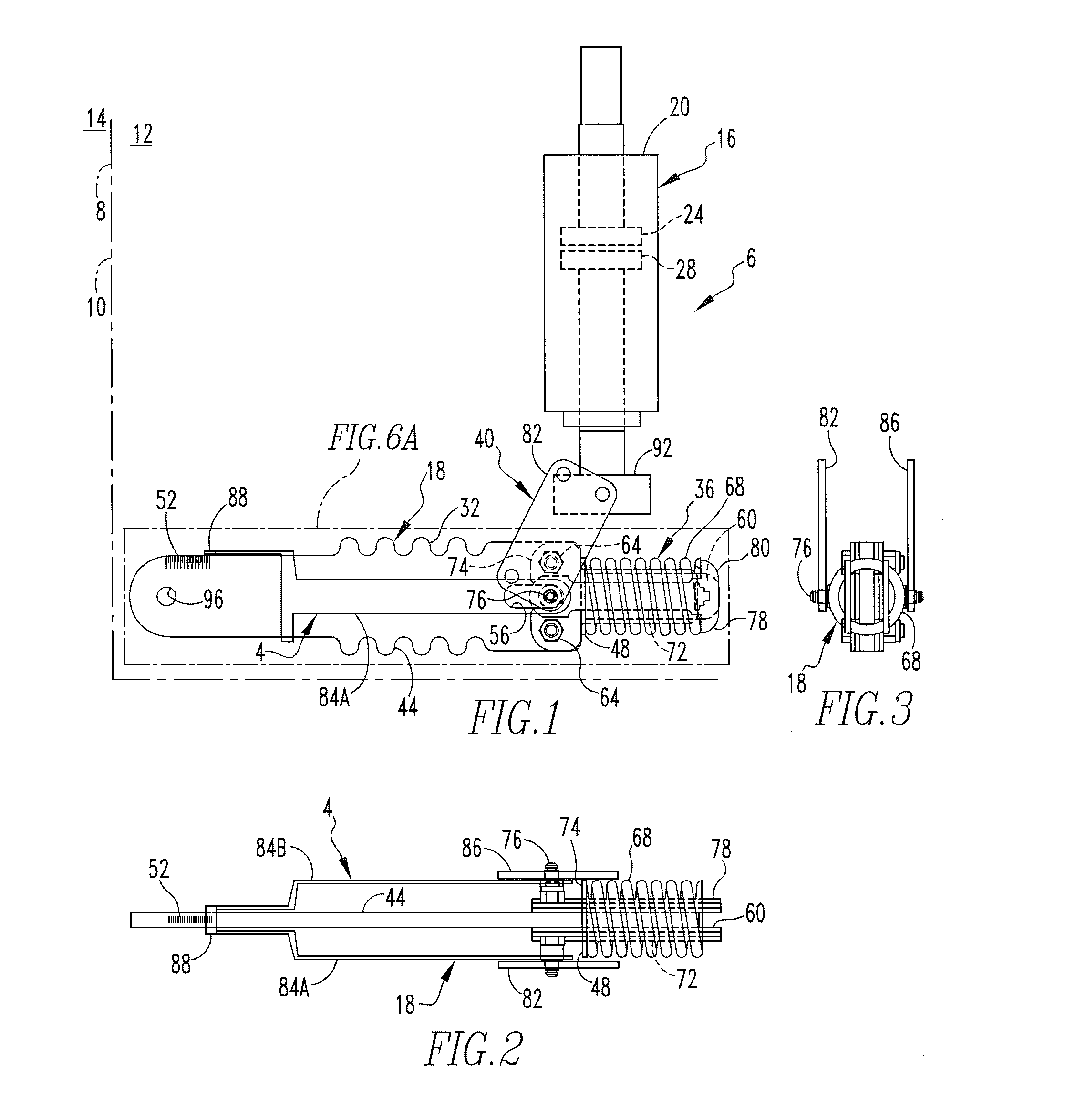
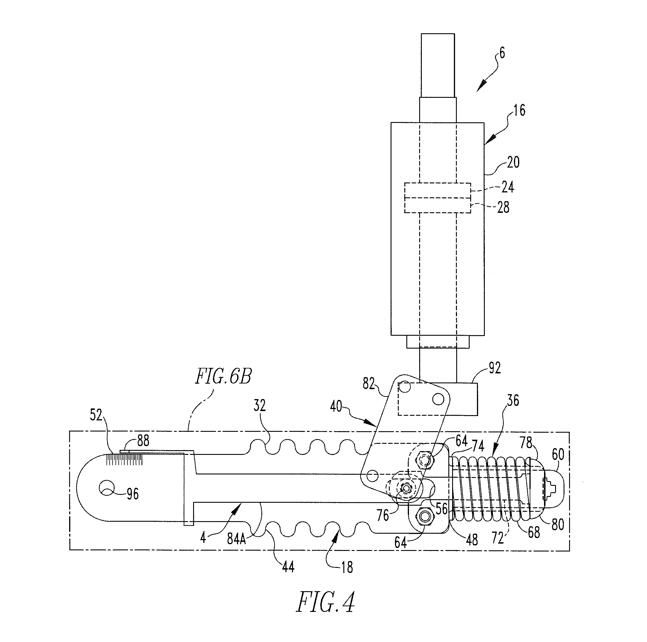
[0019]An improved wear indicator 4 is depicted in FIGS. 1-6C as being a part of an improved circuit interruption apparatus 6 that is in accordance with the disclosed and claimed concept. The wear indicator 4 can be said to function as an indication apparatus that is configured to output an indication of the wear of a set of separable contacts of the circuit interruption apparatus 6, as will be set forth in greater detail below. The circuit interruption apparatus 6 is depicted in FIG. 1 as being situated within a schematically-depicted switchgear cabinet 8 having an access wall 10 that is removable and from where the circuit interruption apparatus 6 and its wear indicator can be observed. An interior of the switchgear cabinet 8 is indicated generally at the numeral 12, and an exterior of the switchgear cabinet 8 is depicted generally at the numeral 14, with both being situated on opposite sides of t...


PUM


Abstract

An improved electrical interruption apparatus provides an improved wear indicator that is configured to depict an amount of wear that has been experienced by a set of separable contacts of a vacuum interrupter. At an easily visible location on a drive rod of the circuit interruption apparatus, the wear indicator indicates the extent to which the set of contacts have degraded. The wear indicator is attached to a spring-loaded over-travel mechanism that engages together the set of electrical contacts.

Description

BACKGROUND[0001]1. Field[0002]The disclosed and claimed concept relates generally to electrical distribution equipment and, more particularly, to an electrical interruption apparatus that includes a wear indicator.[0003]2. Related Art[0004]Electrical distribution equipment is well known and includes many components such as electrical switchgear that may contain therein electrical interruption devices such as circuit breakers, vacuum interrupters, and the like without limitation. Such electrical interruption devices typically include a set of separable contacts which, when separated, desirably open a protected portion of a circuit. It is understood, however, that electrical arcing between the contacts can result in vaporization of the material of the contacts and resultant wear of the contacts. Since such electrical interruption devices typically include a mechanism that is spring loaded and that applies a compressive force to maintain the contacts in their closed position, a loss of...

Claims


Application Information

Patent Timeline
IPC IPC(8): H01H3/46H01H3/38
CPCH01H3/46H01H2239/044H01H2235/01H01H3/38H01H33/666H01H1/0015H01H2033/6667
Inventor RICCIUTI, ANTHONY THOMASFOGLE, THOMAS KENNETHPALMIERI, DANIEL EVAN
Owner EATON INTELLIGENT POWER LIMITED
Learn More