Drum magazine assembly and methods

a drum magazine and drum technology, applied in the field of drum magazine assembly and methods, can solve the problems of reducing reliability, increasing frictional force, and user carries a significant burden in loading and storag

Active Publication Date: 2016-04-14
MAGPUL INDUSTRIES
View PDF11 Cites 15 Cited by
  • Summary
  • Abstract
  • Description
  • Claims
  • Application Information

AI Technical Summary

Benefits of technology

[0016]In another example, a method of controlling the movement of a cartridge in a drum magazine is provided. The method includes causing a follower assembly to bias the cartridge towards an exit in the drum magazine assembly, the follower assembly comprising a plurality of dummy cartridges having a leading dummy cartridge and a last dummy cartridge. The method also includes moving the follower assembly from a retracted configuration within the drum magazine assembly to an extended configuration within a drum assembly of the drum magazine assembly, while allowing the last dummy cartridge to rotate relative to a body of the drum magazine assembly.

Problems solved by technology

In these designs, the track is necessarily limited to a large radius of curvature, resulting in a bulky magazine, as well as an exacerbation of frictional forces due to non-optimal cartridge stacking, and reduction in reliability.
In still other designs, winding of the spring is necessary after loading, meaning the user carries a significant burden with respect to loading and storage.
Yet, if the user under-winds the spring, the cartridges may not feed correctly, requiring further winding by the user, potentially while in the field.
As one example, in currently-available feed towers and drum magazine assemblies, as the magazine approaches the maximum loading capacity, the friction of the cartridges inside the drum does not allow for the spring force to resist the natural tendency of the first cartridge to nose-dive, thus adversely affecting chambering reliability.
In other examples, friction between the drum magazine and the loaded cartridges can cause jamming or delayed responses as the cartridges are moved through the drum magazine, thus reducing the reliability of the magazine and weapon and adversely affecting the feed rate responsiveness—i.e. the response rate of feeding to the rate of fire.
In still other examples, inserting a loaded magazine into a weapon having a closed bolt may cause damage to the cartridges, or prevent the magazine from being inserted correctly, thereby causing misfeeds and / or complete loss or dropping of the magazine from the weapon.
As another example, currently-available magazines exhibit an excessive tolerance in the spacing between the front and rear portions.
Although the excessive tolerance is sometimes unintentional, it is often necessary in currently-available designs.
For example, and using the 0.223 Remington cartridge as just one example, manufacturers of currently-available designs must allow for an overall variance in the cartridge length of 0.095 inches, or 2.413 millimeters, which results in less than ideal cartridge travel within the magazine, including excessive friction and indirectly causing excessive noise and rattling while in the field.
Moreover, when a weapon using currently-available designs is fired, the recoil causes the loaded cartridges to hit the front of the magazine.
These craters tend to exacerbate the friction between the cartridges and the track, because cartridges must not only overcome inherent friction in the system as designed, but also dig each and every bullet tip of each cartridge out of a corresponding crater.

Method used


Image

  • Drum magazine assembly and methods
  • Drum magazine assembly and methods
  • Drum magazine assembly and methods

Examples


embodiment 1

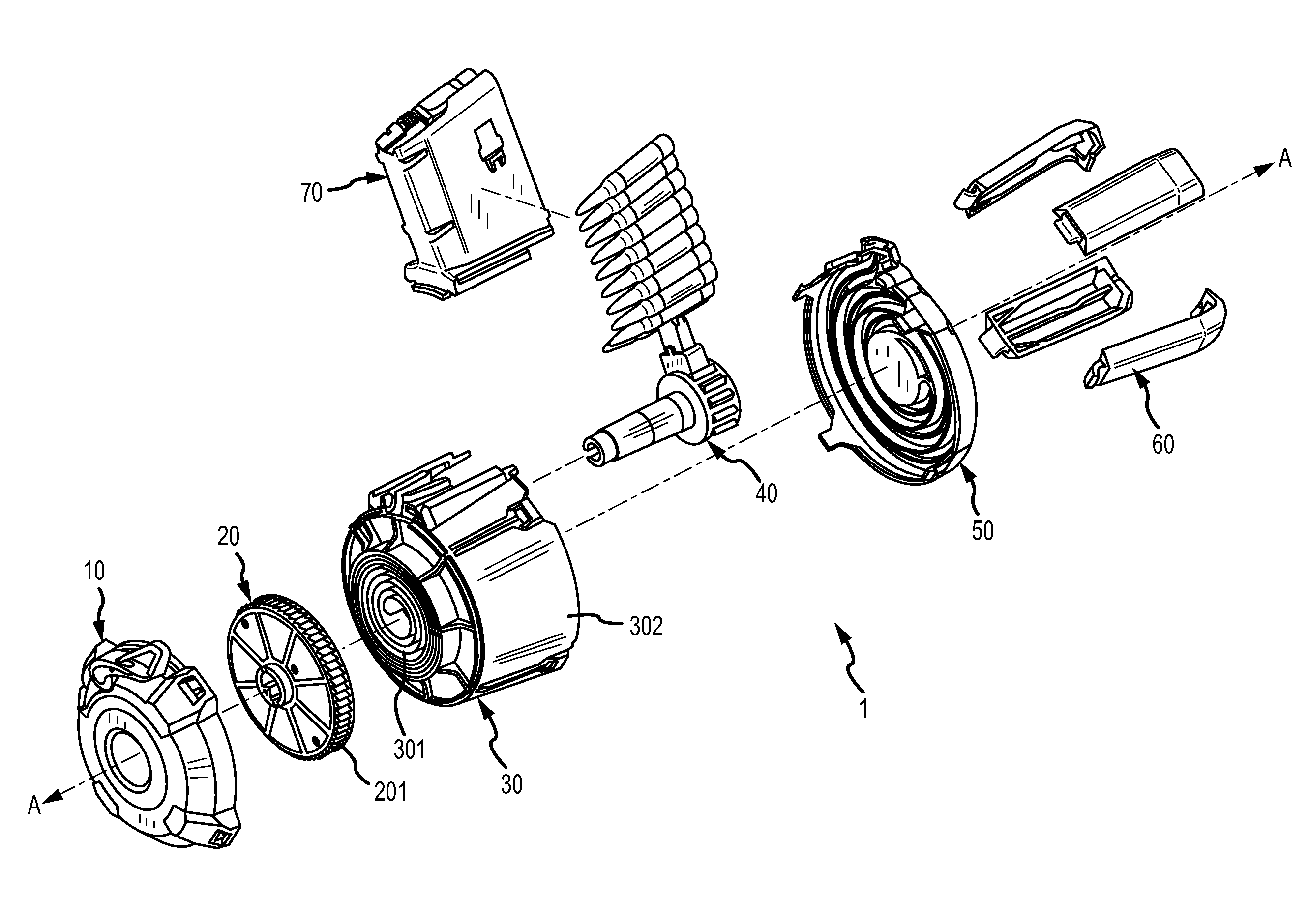
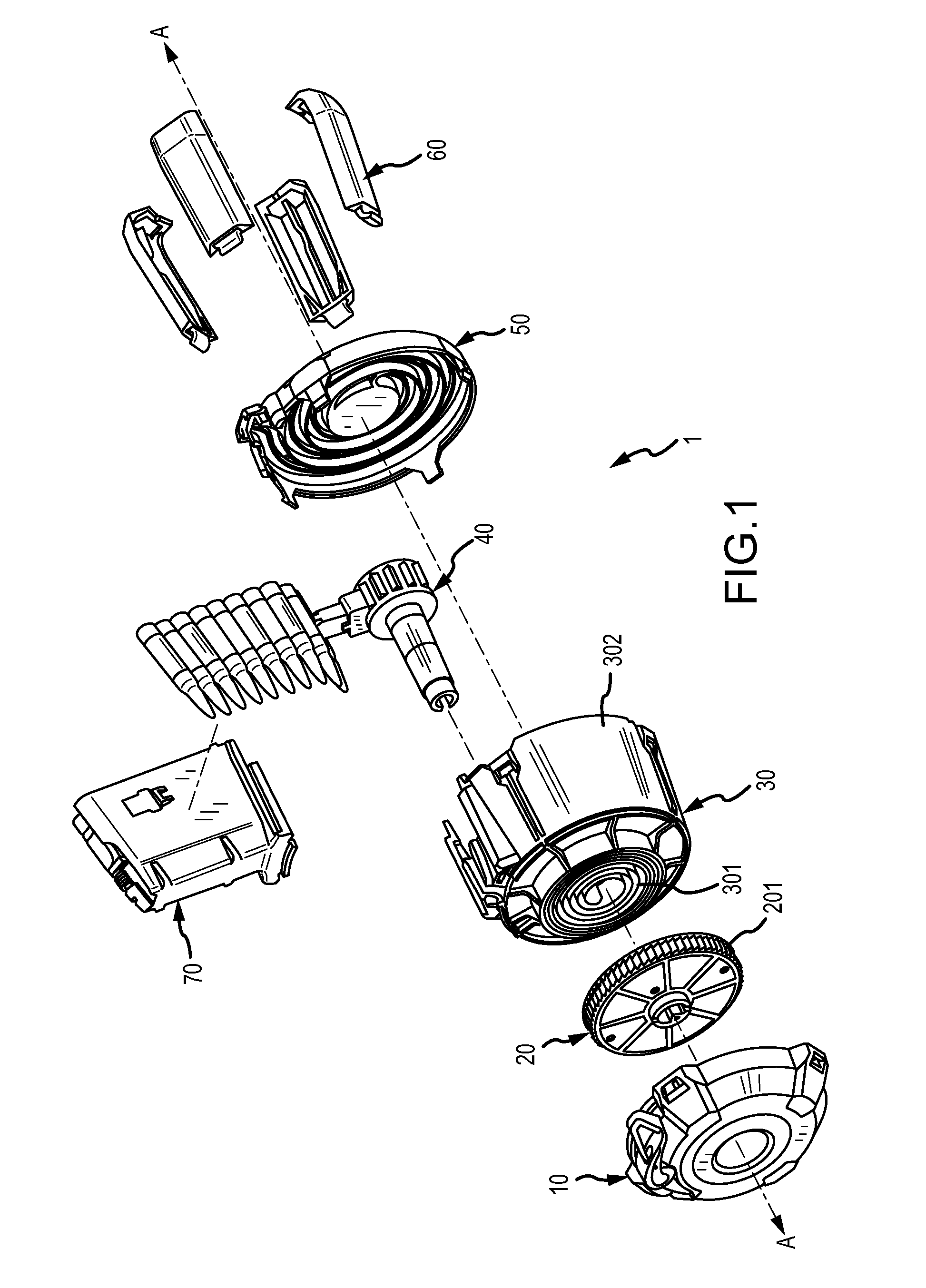
[0154] a drum magazine assembly for a firearm, the drum magazine assembly comprising: a drum assembly comprising a wheel; a spindle assembly; a feed tower assembly; and an advancing mechanism to advance the wheel such that one or more cartridges of ammunition may be loaded after advancing the wheel, the advancing mechanism comprising an arm, a pawl, and a lever, wherein: the arm is configured to pivot about a first pivot axis to drive the pawl about the first pivot axis, the first pivot axis defined by the spindle assembly; the pawl is configured to pivot about a second pivot axis between a free position and an engage position, the second pivot axis defined by a distal section of the arm; the pawl is further configured to selectively engage the wheel when the pawl is in the engage position; the lever is configured to pivot the pawl about the second pivot axis; the lever is further configured to move relative to the second pivot axis between a closed position and an open position.

[01...

embodiment 4

[0157] the drum magazine assembly of embodiment 1, wherein: the lever comprises an advancement lock to prevent the pawl from engaging the wheel when the lever is in the closed position.

[0158]Embodiment 5: the drum magazine assembly of embodiment 4, wherein: the advancement lock comprises configured clearance groove to provide a clearance to selectively allow advancement of the wheel when the lever is in the open position.

embodiment 5

[0159]Embodiment 6: the drum magazine assembly of embodiment 5, wherein: the lever comprises a lever lock configured to prevent the lever from being moved from the closed position to the open position when the drum magazine assembly is installed in a weapon.


PUM


Abstract

A drum magazine assembly and methods are described. A drum assembly has a follower assembly, a drum body, a spring assembly, and a feed tower assembly. The follower assembly biases cartridges towards an exit of the feed tower assembly. The follower assembly has a plurality of dummy cartridges, the plurality of dummy cartridges having a leading dummy cartridge and a last dummy cartridge, and a plurality of links including a leading link and a last link. The last dummy cartridge rotates relative to the last link and the leading link, and the leading dummy cartridge has a bolt catch engagement feature.

Description

CROSS-REFERENCE TO RELATED APPLICATIONS[0001]This application claims priority to U.S. Provisional Application No. 62 / 063,546 filed Oct. 14, 2014 and entitled “DRUM MAGAZINE ASSEMBLY AND METHODS,” the entire disclosure of which is hereby incorporated by reference for all proper purposes.COPYRIGHT[0002]A portion of the disclosure of this patent document contains material that is subject to copyright protection. The copyright owner has no objection to the facsimile reproduction by anyone of the patent disclosure, as it appears in the Patent and Trademark Office patent files or records, but otherwise reserves all copyright rights whatsoever.FIELD OF THE INVENTION[0003]The present invention relates to firearms, and, more specifically, magazines for firearms.BACKGROUND OF THE INVENTION[0004]Ammunition magazines, and, more particularly, drum magazines, are well known in the art of firearms. An open end, which is the feed portion or feed end, is the portion that interfaces directly with a w...

Claims


Application Information

Patent Timeline
Patent Type & Authority Applications(United States)
IPC IPC(8): F41A9/75F41A9/70
CPCF41A9/70F41A9/75F41A9/61F41A9/73F41A9/65
Inventor ROBERTS, TIMOTHY ERICMAYBERRY, MICHAEL T.NAKAYAMA, BRIAN L.FITZPATRICK, RICHARD M.NAKAYAMA, ERICBENNETT, WILLIAM BRADLEY
Owner MAGPUL INDUSTRIES
Why Eureka
Try Eureka