Golf club head of iron or wood type

a golf club and iron or wood technology, applied in golf clubs, racket sports, golf, etc., can solve the problems of affecting the quality of golf clubs, so as to achieve the effect of convenient manufactur

Inactive Publication Date: 2003-10-09
SKIS ROSSIGNOL
View PDF11 Cites 159 Cited by
  • Summary
  • Abstract
  • Description
  • Claims
  • Application Information

AI Technical Summary

Benefits of technology

[0013] Another objective of the invention is to give the club head a structure that allows the deformation of the striking face to be adjusted, while at the same time being easy to manufacture.
[0016] In other words, the head according to the invention includes a spring-forming leaf which is firmly fixed, for example by screwing or welding, to the sole or alternatively the lateral walls or the crown wall in the case of a wood. The other end of this leaf exerts load on the internal face of the wall of the striking face without being fixed to this wall. In that way, during the deformation movements of the striking face, the end of the spring leaf remains in contact with the back of the striking face, and therefore produces a continuous and progressive effect. The region of contact between the leaf and the striking face can move slightly without generating excessive stresses in the actual wall of the striking face. As the spring leaf is fixed only at one of its ends, its stiffness is practically constant regardless of its deformation.
[0017] In addition, such a device, by limiting the vibrations of the striking face, makes it possible to correct the sound resulting from impact of the ball on the club.
[0018] To improve the properties of this contact, it is possible to make provision for the free end of the elastic leaf to be curved, so that contact between the leaf and the striking face is tangential.

Problems solved by technology

In addition, the disadvantages associated with these solutions lie in the fact that the deformation of the striking face is altered abruptly when the back of the striking face comes into contact with the element placed for that purpose in the cavity.
This discontinuity in the deformation of the striking face may cause certain vibrations to arise.
Such a construction is relatively complicated because it combines the bending effect with the warping effects of a leaf constrained at its ends.
These devices have the disadvantage of generating significant vibration and have no real influence on the trampolining effect, because the latter is determined solely by the inherent characteristics of the striking face, once the additional mass detaches therefrom.

Method used


Image

  • Golf club head of iron or wood type
  • Golf club head of iron or wood type
  • Golf club head of iron or wood type

Examples


Embodiment Construction

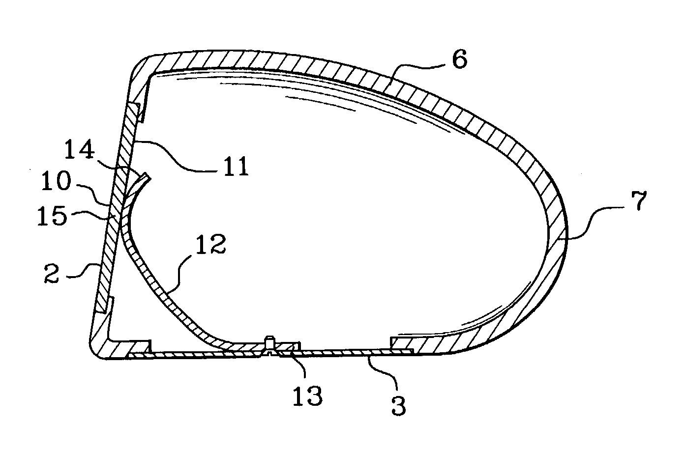
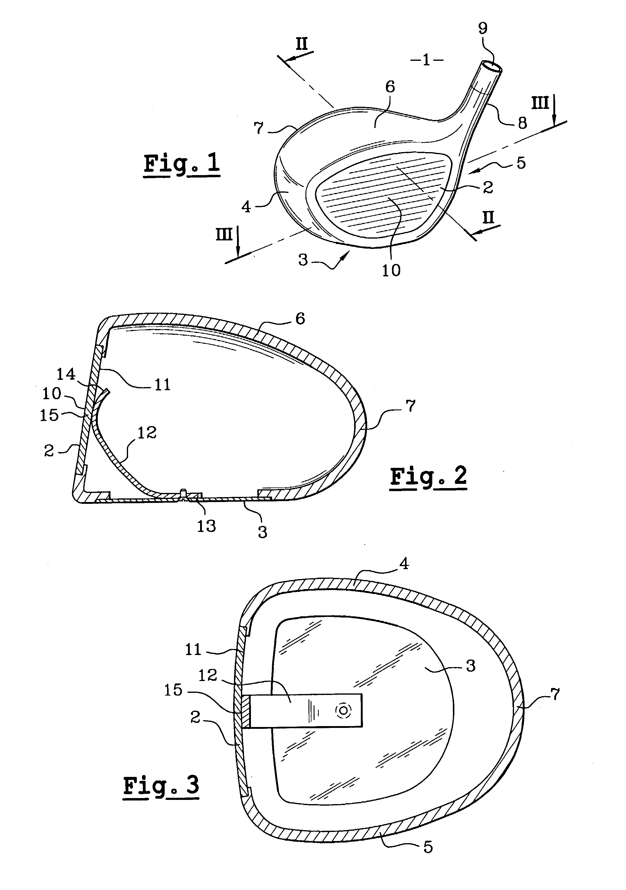
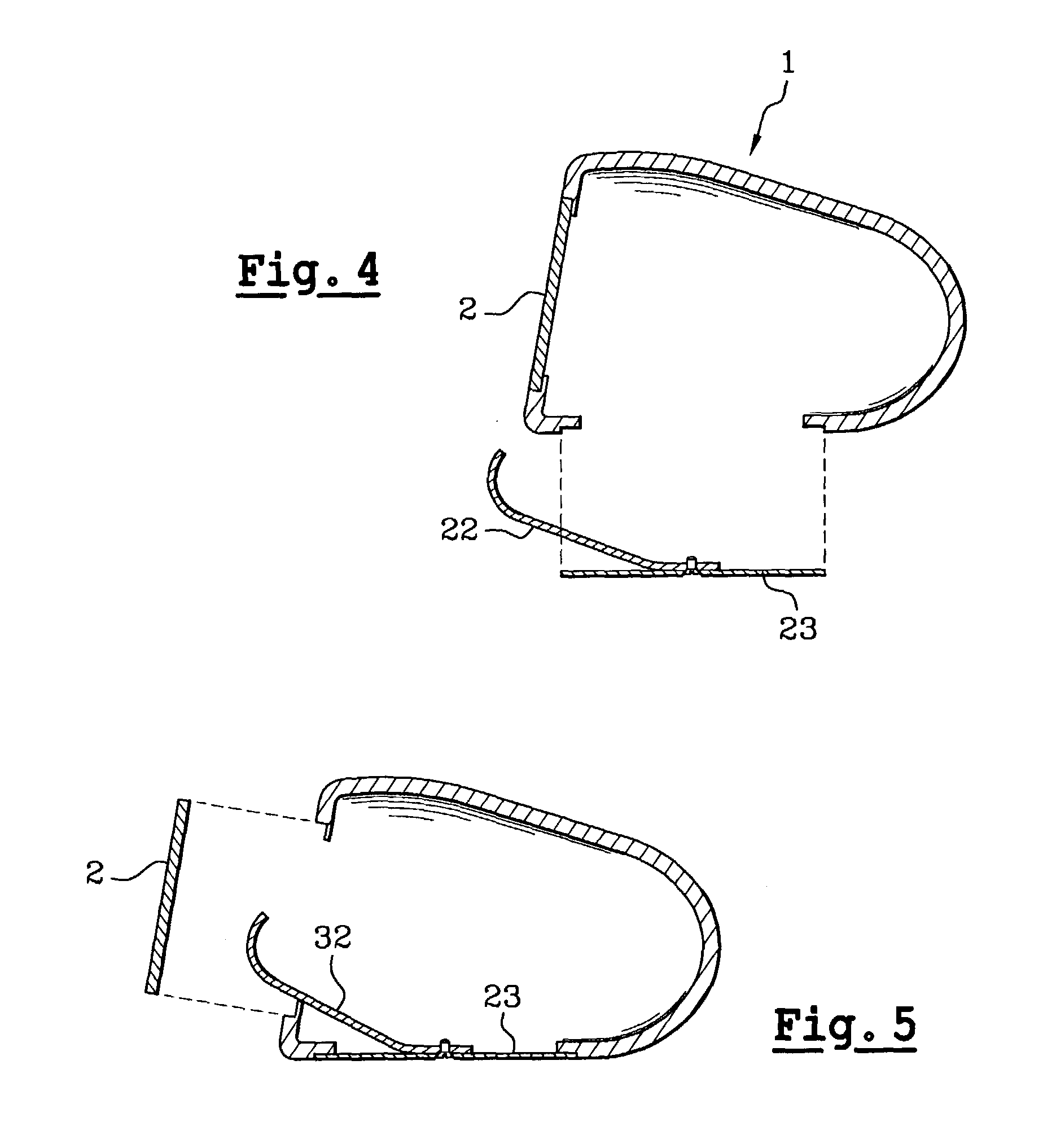
[0037] As already mentioned, the invention relates to a golf club head (1). FIG. 1 depicts a head of the "wood" type. Such a head comprises a striking face (2), a sole (3), lateral faces (4, 5), a crown face (6) and a back wall (7) defined in the continuity of the lateral faces (4, 5), of the crown face (6) and of the sole (3). The striking face is fixed rigidly to the rest of the head, for example by welding around its periphery. This head (1) also comprises a hosel (8) intended to accommodate, inside a housing (9), the shaft of the club.

[0038] Traditionally, the striking face (2) has a horizontally scored surface. The point (10) situated on the striking face and corresponding to the optimum point of impact is generally known as the sweet spot.

[0039] In the form illustrated in FIG. 2, it can be seen that the sole (3) has a metal leaf (12) fixed by one of its ends (13), for example by screwing. This screwing may be done as in the embodiment illustrated through the sole by at least o...


PUM


Abstract

Head (1) of a golf club of the "wood" or "iron" type, having a wall forming the striking face (2), at least one wall adjacent the wall forming the striking face (2), namely in particular the wall of the sole (3), and which also comprises an elastic leaf (12) one end (13) of which is fixed to one of the walls (6) adjacent the wall forming the striking face (2), and the free other end (14) of which presses the preload against the back face (11) of the wall of the striking face (2).

Description

[0001] The invention relates to the field of golf. It is aimed more specifically at a novel structure of the head of a golf club of the "wood" or "iron" type. The invention makes it possible to optimize the trampolining effects of the striking face.PRIOR ART[0002] In general, golf clubs the heads of which are initially made of solid wood before they were made even of hollow metal or of composite are known as "woods".[0003] The invention protects the type of clubs known as woods the interior of which is hollow. The striking face of these woods is relatively weakly inclined with respect to the vertical, which means that such clubs are dedicated to the taking of long shots.[0004] More specifically, the head of a "wood" has an internal cavity delimited by various walls. One of these walls forms the striking face. Among the walls adjacent the one forming the striking face are the wall forming the sole and the side walls and a crown wall. The rear of the cavity is closed off either by a r...

Claims


Application Information

Patent Timeline
Patent Type & Authority Applications(United States)
IPC IPC(8): A63B53/04A63B59/00
CPCA63B53/04A63B59/0092A63B53/047A63B2053/0416A63B53/0466A63B2053/0433A63B60/54A63B53/0416A63B53/0433A63B60/00
Inventor FAGOT, JACQUES
Owner SKIS ROSSIGNOL
Why Eureka
Try Eureka