Method and device for controlling the light emission of a rear light of a vehicle

Active Publication Date: 2016-04-21
VOLKSWAGEN AG
View PDF3 Cites 5 Cited by
  • Summary
  • Abstract
  • Description
  • Claims
  • Application Information

AI Technical Summary

Benefits of technology

The present invention provides a method and device for improving the signal effect of a vehicle's rear light, while optimizing the installation space. This is achieved by turning off part of the first light function and providing a separate partial emitting surface for the first function that is illuminated during the switchover to the second light function. This design creates an association between the two light functions and provides a visually appealing appearance to the rear light. The method can be followed by a design that merges the emitting surfaces or separates them, resulting in a high recognition value for the vehicle.

Problems solved by technology

A problem arises in the redesigning of vehicles that because of the desired aerodynamics and the desired design, the installation space conditions for lighting equipment, particularly for rear lights, headlights, and reflectors, are very limited dimensionally.
Further, the problem arises that the cost of the production of the lights is to be as low as possible.

Method used


Image

  • Method and device for controlling the light emission of a rear light of a vehicle
  • Method and device for controlling the light emission of a rear light of a vehicle
  • Method and device for controlling the light emission of a rear light of a vehicle

Examples


Embodiment Construction

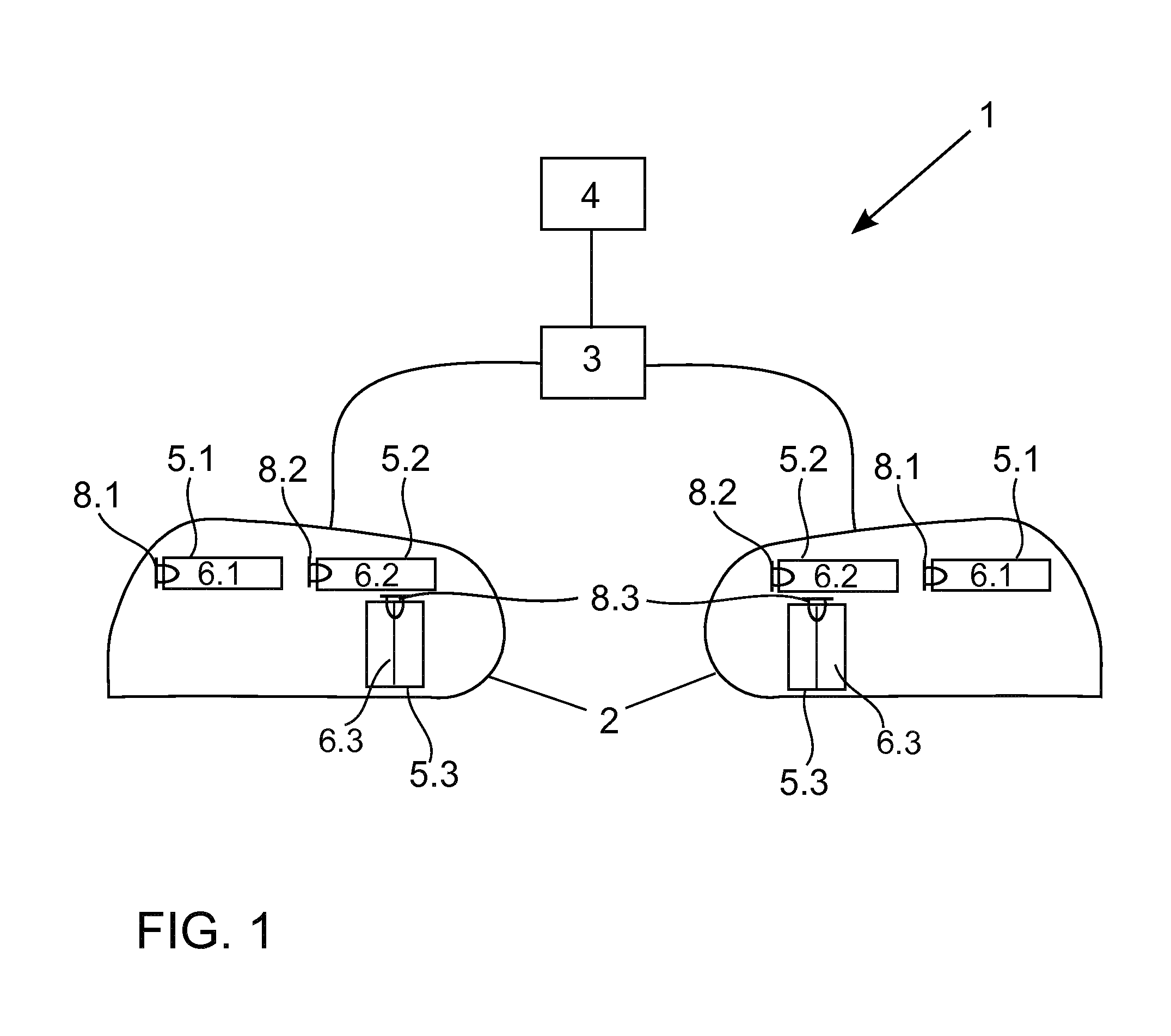
[0036]An exemplary embodiment of device 1 of the invention is described with reference to FIG. 1.

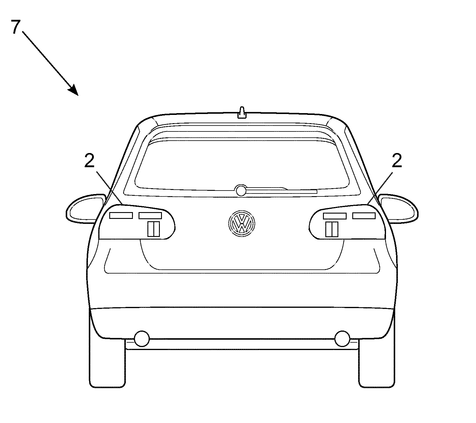
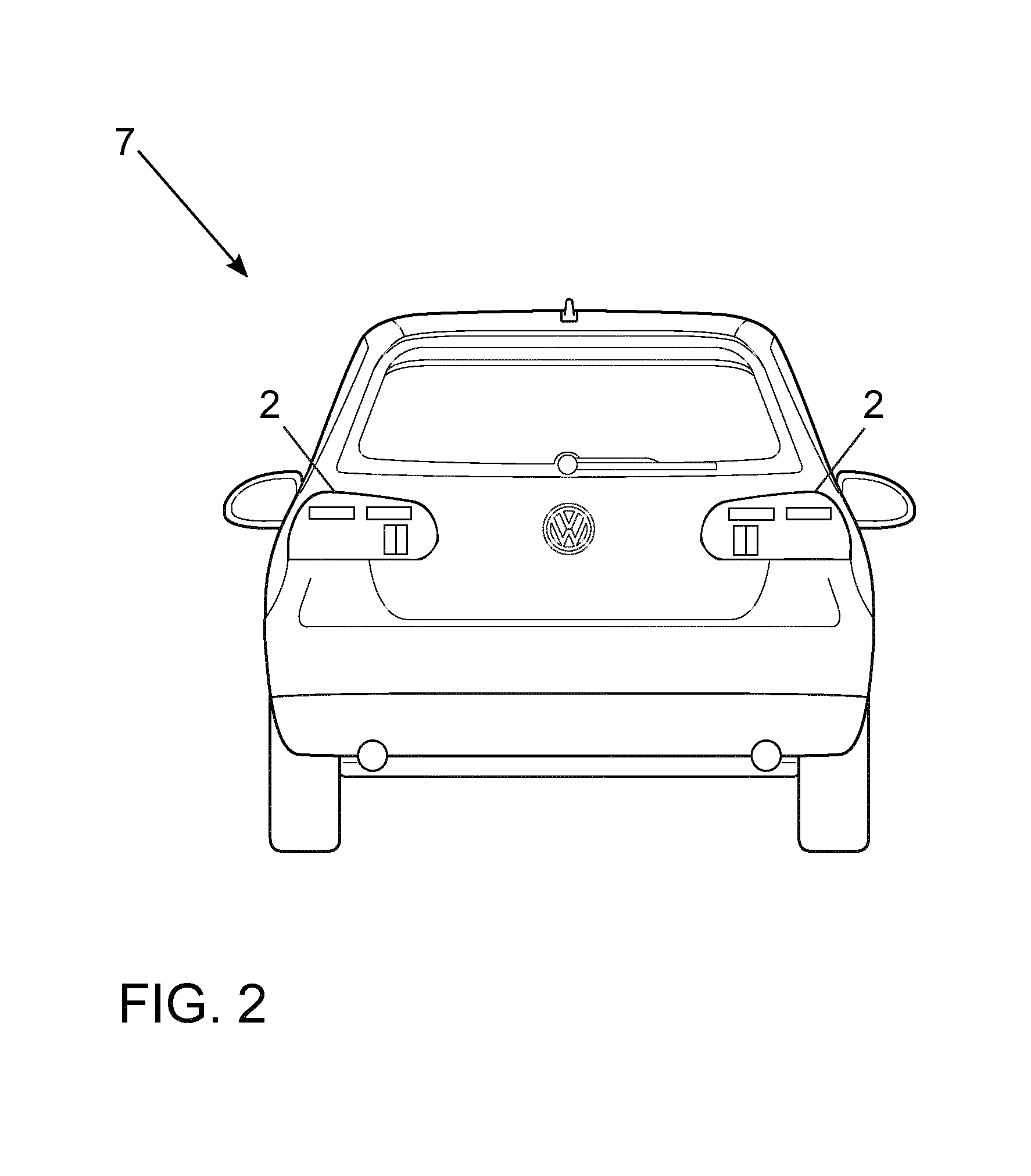
[0037]Device 1 of the invention comprises two rear lights 2, which in turn comprise a plurality of optical components 5 and 8. Optical components 5 and 8 comprise optical fibers 5 and LEDs 8. LEDs 8 couple light into optical fibers 5. The decoupling surfaces of optical fibers 5 function as emitting surfaces 6 of rear lights 2. Emitting surface 6 is divided into three partial emitting surfaces 6.1, 6.2, and 6.3. Optical components 5 are arranged furthermore so that partial emitting surfaces 6.1 and 6.2 of optical fibers 5.1 and 5.2 emit light as horizontal lines. Partial emitting surface 6.3, in contrast, is arranged so that it emits light as a vertical line. Partial emitting surfaces 6.1 and 6.2 are therefore perpendicular to partial emitting surface 6.3. Partial emitting surfaces 6.1, 6.2, and 6.3 further are arranged separately from one another; therefore they are not in contact.

[0038]...


PUM


Abstract

A method and device for controlling a light emission of a rear lamp of a vehicle. The rear lamp includes optical components having emission surfaces having at least three partial emission surfaces. At least a first and a second light function can be produced by the light emission of the emission surfaces. After a switchover process from the first to the second light function, the first partial emission surface, which emits light for the first light function, emits no light, the second partial emission surface, which emits light for the first light function, continues to emit light, and the third partial emission surface, which emits no light for the first light function, emits light.

Description

[0001]This nonprovisional application is a continuation of International Application No. PCT / EP2014 / 061300, which was filed on Jun. 2, 2014, and which claims priority to German Patent Application No. 10 2013 010 333.9, which was filed in Germany on Jun. 20, 2013, and which are both herein incorporated by reference.BACKGROUND OF THE INVENTION[0002]1. Field of the Invention[0003]The present invention relates to a method for controlling a light emission of a rear light of a vehicle, whereby the rear light comprises optical components having emitting surfaces with at least three partial emitting surfaces and whereby at least a first and a second light function can be generated via the light emission of the emitting surfaces. Further, the invention relates to a device for controlling the light emission of a rear light of a vehicle.[0004]2. Description of the Background Art[0005]A problem arises in the redesigning of vehicles that because of the desired aerodynamics and the desired design...

Claims


Application Information

Patent Timeline
IPC IPC(8): B60Q1/00B60Q1/34B60Q1/46B60Q1/44H05B44/00
CPCB60Q1/0076B60Q1/444B60Q1/0011B60Q1/46B60Q1/34B60Q1/2607
Inventor SOLA GOMFAUS, ANDREUWERNER, MICHAELMUELLER, MICHAELTHAMM, MATHIASMENSCH, DANIELKIEL, HENNING
Owner VOLKSWAGEN AG
Why Eureka
Try Eureka