Production machine or machine tool and method for operating a production machine or machine tool

Active Publication Date: 2016-05-12
SIEMENS AG
View PDF6 Cites 0 Cited by
  • Summary
  • Abstract
  • Description
  • Claims
  • Application Information

AI Technical Summary

Benefits of technology

[0025]In a particular embodiment of the invention, the temporarily-storing component combines several temporarily-stored messages together and then forwards the combined messages at a later point in time that is prescribed relative to a communications cycle time of the machine. The temporarily-storing component still fits seamlessly into the previous concept of real-time communication in accordance with the time-slot method when forwarding such combined messages. With the combined temporarily-stored messages, pauses that are otherwise always present between individual messages communicated using the time-slot method disappear. By the combination of several messages, the cycle time is optimally utilized and the result is that within the same cycle time it is possible to communicate more payload data, or to communicate additional messages.
[0026]Advantageously, in accordance with the invention, a message is forwarded to a temporarily-storing component at a first time point relative to the cycle time and from the temporarily-storing component at a different, second time point relative to the cycle time, these two trans

Problems solved by technology

Any infringement of the cycle/reaction time criteria referred to below as the “cycle time” for short, will inevitably result in the invalidity of the transmitted data concerned.
This sending takes place even then when the prerequisites may not be present, for example because data items, in particular locally recorded measured values, are not yet available.
Although the sending of messages in the time-slot method is an established and proven technique, there are in practice certainly still some problems.
Thus, a network with its components connected for communication purposes often includes areas with conditions which are mechanically or electrically more difficult.
One example of such more difficult mechanical conditions is tra

Method used


Image

  • Production machine or machine tool and method for operating a production machine or machine tool
  • Production machine or machine tool and method for operating a production machine or machine tool
  • Production machine or machine tool and method for operating a production machine or machine tool

Examples


Embodiment Construction

[0037]Throughout all the figures, same or corresponding elements may generally be indicated by same reference numerals. These depicted embodiments are to be understood as illustrative of the invention and not as limiting in any way. It should also be understood that the figures are not necessarily to scale and that the embodiments are sometimes illustrated by graphic symbols, phantom lines, diagrammatic representations and fragmentary views. In certain instances, details which are not necessary for an understanding of the present invention or which render other details difficult to perceive may have been omitted.

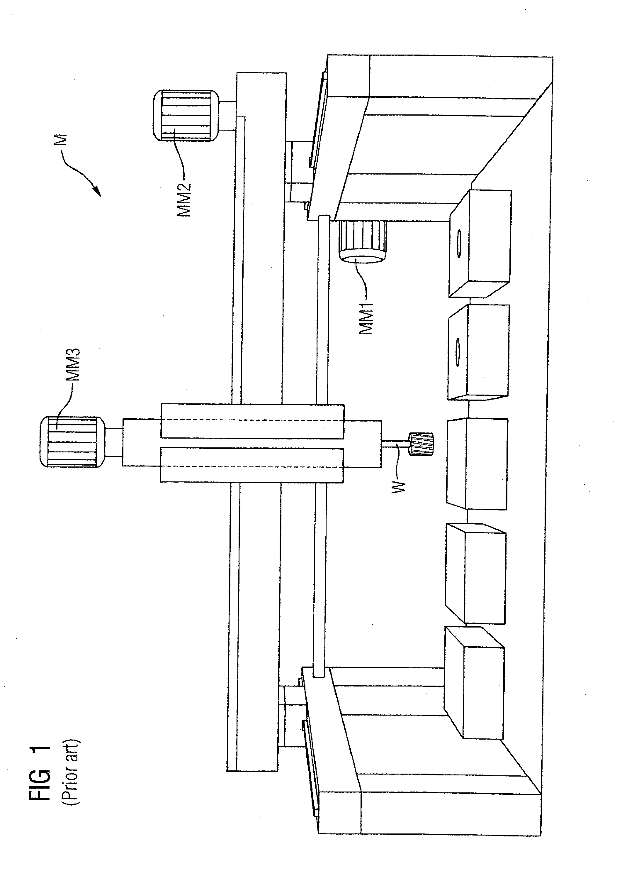
[0038]Turning now to the drawing, and in particular to FIG. 1, there is shown an example of a production machine or machine tool a facility, referred to below for short as a machine M, wherein three drive units, motor modules MM1, MM2, and MM3. These motor modules MM1-MM3 and the power components which they incorporate, not identified separately here, move a tool holder W, i...


PUM


Abstract

An automated machine wherein messages exchanged between components of the machine are forwarded to at least one component at a first time point that temporarily stores them and from that component to a central unit at a second time point is disclosed. Said first time point preceding said second time point within the framework of a cycle time of the automated machine. The time points are determined relative to that cycle time and provided to respective components in conjunction with a startup of the automated machine. The component temporarily storing messages forwards them in the manner of a layer-3 switch. This message forwarding is driven by the respective time points, rather than event-driven, can operate seamlessly in existing systems wherein communications are time-slot controlled, and decouples the components so that real-time communications within the machine can be optimized.

Description

CROSS-REFERENCES TO RELATED APPLICATIONS[0001]This application claims the priority of European Patent Application, Serial No. 14192315.1, filed Nov. 7, 2014, pursuant to 35 U.S.C. 119(a)-(d), the disclosure of which is incorporated herein by reference in its entirety as if fully set forth herein.BACKGROUND OF THE INVENTION[0002]The invention relates to a program-controlled automated machines, and a method for the operation of such a machine. In particular, the invention relates to a production machine or machine tool, such as a program-controlled automation system having an industrial robot.[0003]The following discussion of related art is provided to assist the reader in understanding the advantages of the invention, and is not to be construed as an admission that this related art is prior art to this invention.[0004]Production machines and machine tools, referred to herein as “machines”, for short, are known per se. A printing machine is one example of a production machine. The ter...

Claims


Application Information

Patent Timeline
IPC IPC(8): G05B19/042
CPCG05B2219/25022G05B19/0421G05B19/4148G05B2219/34298G05B19/042
Inventor DOTTERWEICH, BERNDGROSS, MARKUSKASDORF, OSWALDVON DER BANK, MICHAEL
Owner SIEMENS AG
Why Eureka
Try Eureka