Pneumatic detector assembly with bellows

a technology of pneumatic detectors and bellows, which is applied in the direction of fire alarms, instruments, fluid pressure measurement, etc., can solve the problems of difficult manufacturing, many parts, and complex design of pneumatic detectors

Active Publication Date: 2016-04-21
KIDDE TECH
View PDF0 Cites 9 Cited by
  • Summary
  • Abstract
  • Description
  • Claims
  • Application Information

AI Technical Summary

Problems solved by technology

However, such pneumatic detectors may have complex...

Method used


Image

  • Pneumatic detector assembly with bellows
  • Pneumatic detector assembly with bellows
  • Pneumatic detector assembly with bellows

Examples


Embodiment Construction

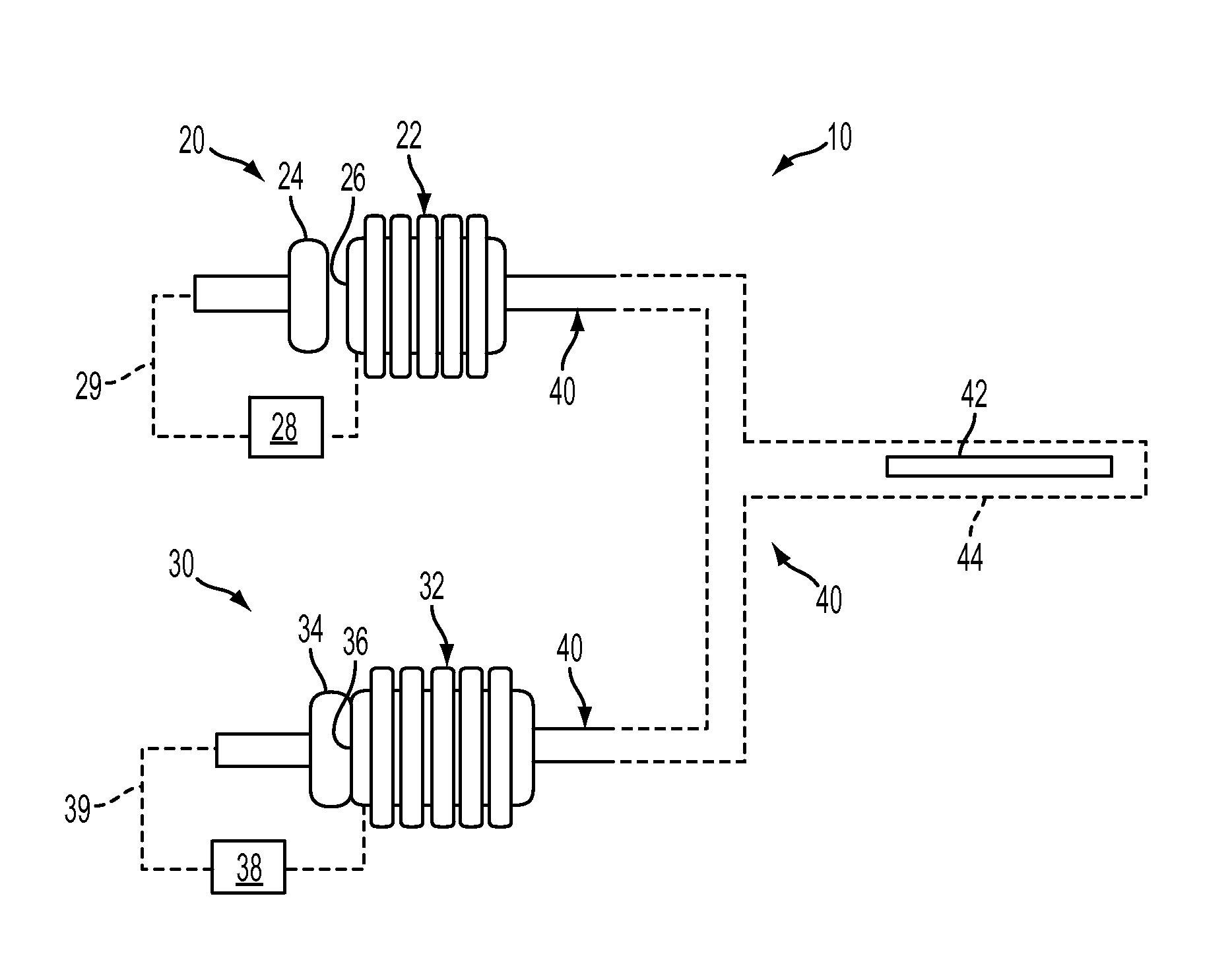
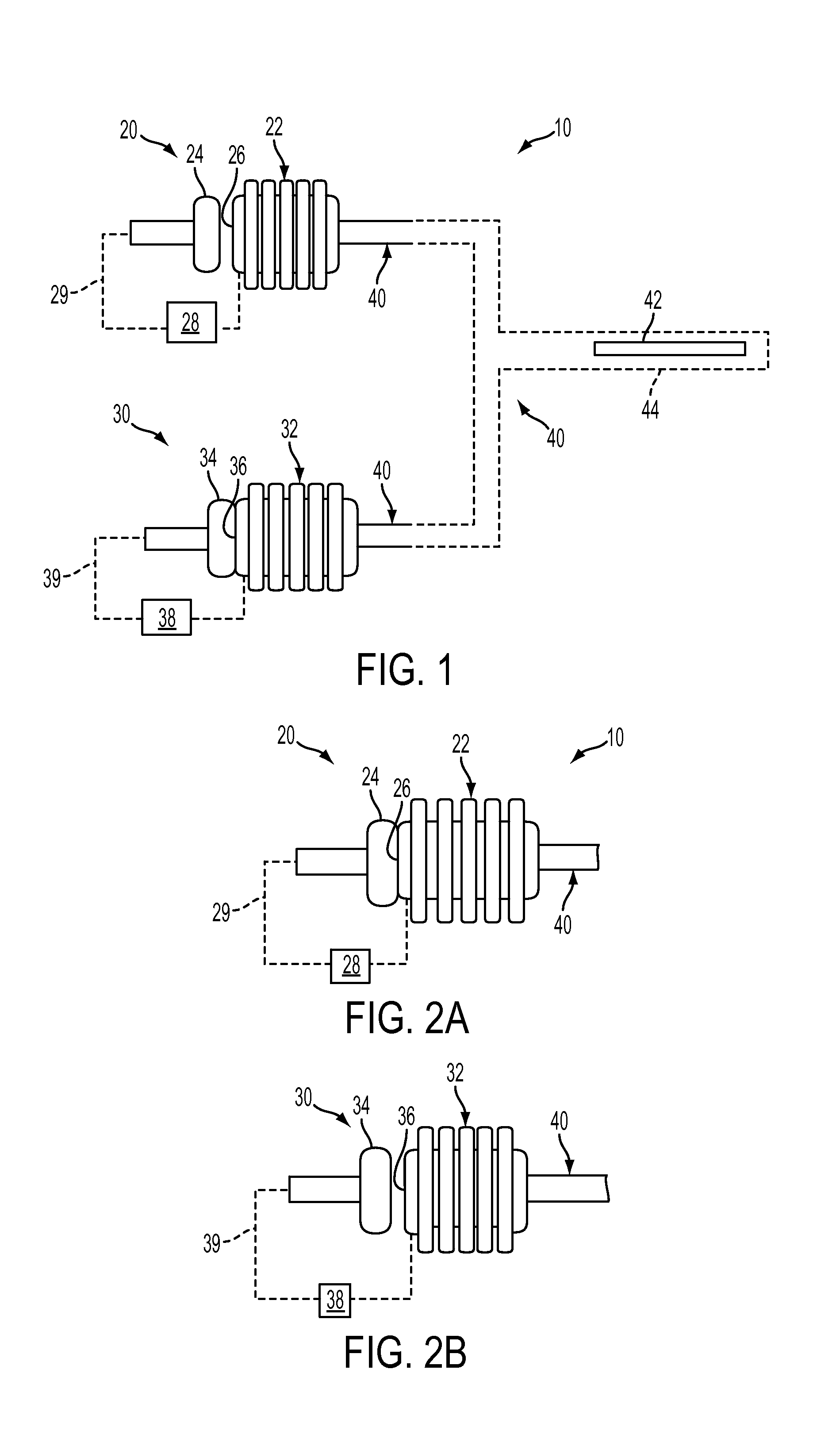
[0018]FIGS. 1, 2A, and 2B illustrate an exemplary pneumatic detector assembly 10 that generally includes an alarm switch 20, a fault (integrity) switch 30, and a sensor tube 40. FIG. 1 illustrates switches 20, 30 in normal operating positions, and FIGS. 2A and 2B illustrate switches 20, 30 in alarm / fault positions.

[0019]Although pneumatic detector assembly 10 is illustrated with one alarm switch 20 and integrity switch 30, assembly 10 may have any number or combination of switches 20, 30. Alarm switch 20, fault switch 30, and at least a portion of sensor tube 40 may be packaged in one or more hermetically sealed housings (not shown).

[0020]Alarm switch 20 is coupled to sensor tube 40 and includes a bellows 22 and a contact pin 24. In the exemplary embodiment, the location of contact pin 24 is adjustable. However, contact pin 24 may be fixed in a desired location. Bellows 22 includes a contact face 26 and is connected to a power source 28. A power return 29 is connected to contact pin...


PUM


Abstract

In one aspect, a pneumatic detector assembly is provided. The assembly includes a housing, a sensor tube, a contact pin, and at least one switch having a bellows operatively associated with the sensor tube and the contact pin. The bellows is configured to move into and out of contact with the contact pin based on a pressure in the sensor tube.

Description

BACKGROUND OF THE INVENTION[0001]Reliable fire detection is critical for many aircraft. Common thermal fire detector types include point thermocouple, point thermistor, continuous thermocouple, continuous thermistor, resistance wire, and pneumatic tube.[0002]Some pneumatic tube detector systems include a titanium or vanadium wire inserted into a capillary sensor tube. The wire is exposed to and absorbs high temperature energy and pressurized hydrogen gas and subsequently stores the gas as the wire cools to form a hydrogen saturated wire. This saturated wire is inserted into a sensor tube, which is pressurized with an inert gas, and sealed at both ends to form a pressure vessel, which can be used as a pneumatic detector. One of the ends of the pressure vessel is incorporated into a housing that includes a plenum, where alarm and integrity switches are located.[0003]When the sensor tube portion of the pneumatic detector is exposed to high temperature, the pressure is increased inside ...

Claims


Application Information

Patent Timeline
IPC IPC(8): G08B17/04G08B17/06
CPCG08B17/06G08B17/04G01L7/06G08B17/10G01L7/063G01L9/0033G01L19/12G08B29/043
Inventor FRASURE, DAVIDWALLACE, STEVENSTANDIFER, WILLIAM BRETT
Owner KIDDE TECH
Why Eureka
Try Eureka