Converter

a technology of converters and converters, applied in the field of converters, can solve the problems of heat loss, power parts that have not been miniaturized and lightweight compared, and heat loss of switching devices, and achieve the effect of simple circuit configuration and convenient soft-switch

Active Publication Date: 2016-04-21
SKAICHIPS CO LTD
View PDF7 Cites 10 Cited by
  • Summary
  • Abstract
  • Description
  • Claims
  • Application Information

AI Technical Summary

Benefits of technology

[0013]Another object of the present disclosure is to provide a converter that facilitates soft-switching using a simple circuit configuration.

Problems solved by technology

In accordance with current trends, in terms of electronic and communication devices, a system part has been rapidly miniaturized and lightweight together with the development of a semiconductor integrated circuit, but a power part has not been miniaturized and lightweight compared with what expected due to an energy storage device such as an inductor, a capacitor, etc.
However, when a switching frequency is increased using a high-speed semiconductor switching device, etc., switching loss and a heating issue of the switching device are caused.
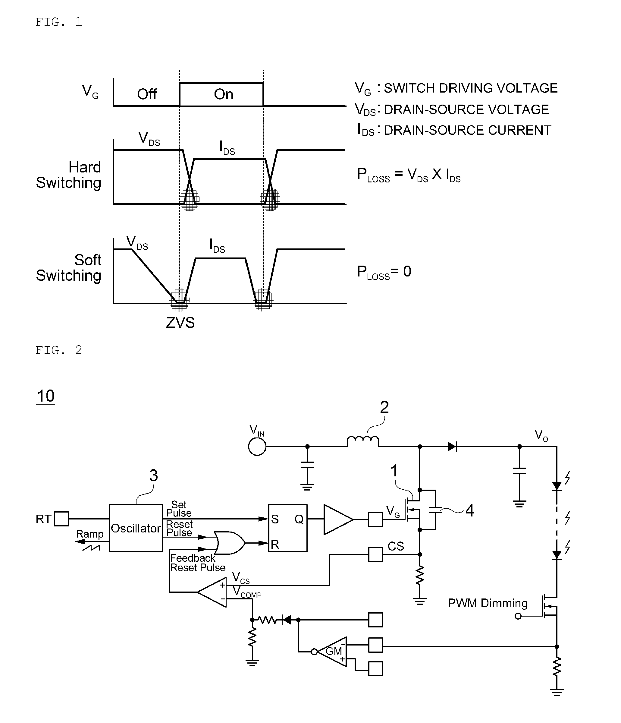
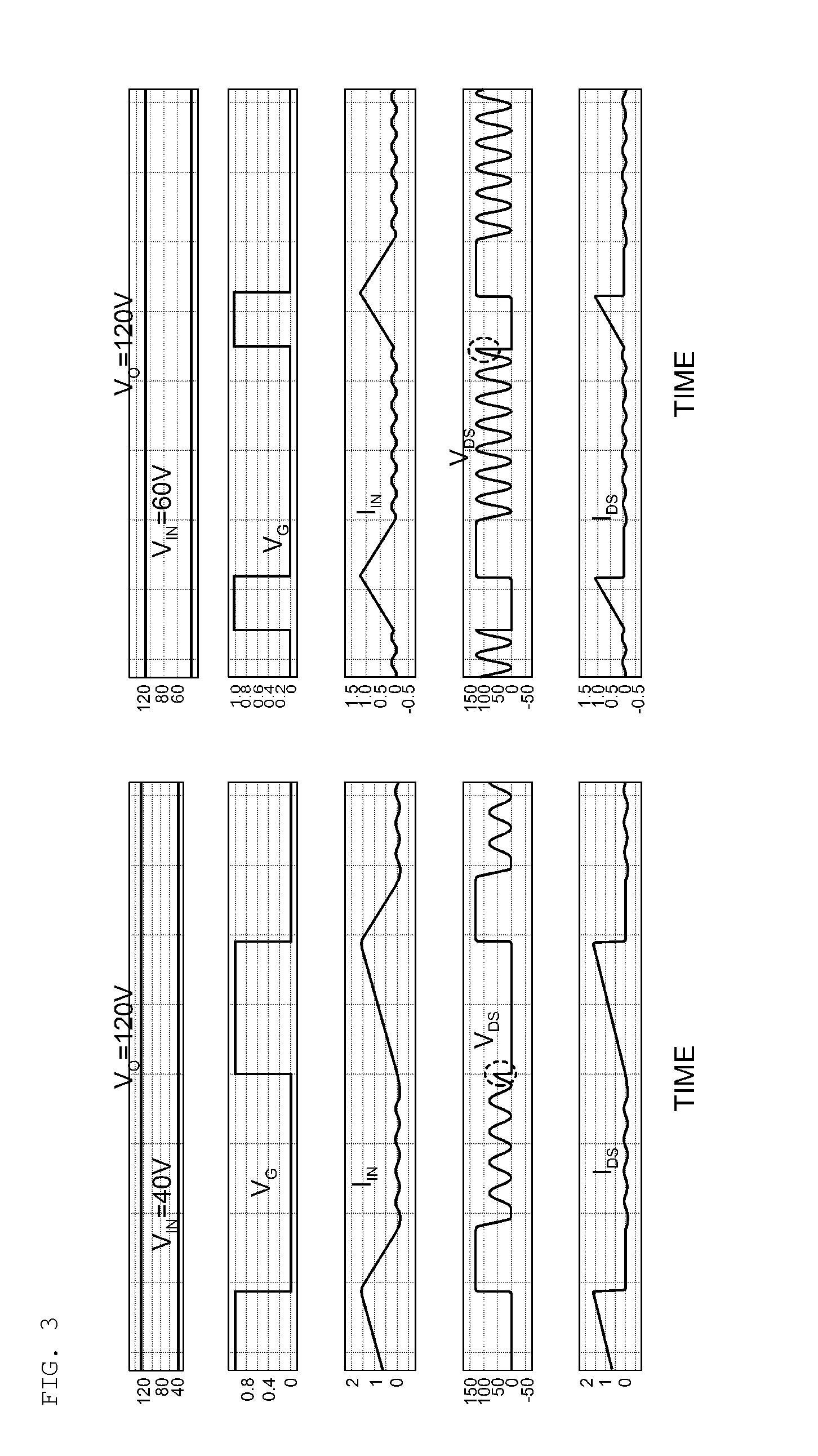
However, according to the soft-switching method, when an output voltage of a converter does not reach a sufficient level, a voltage between opposite ends of the switching device does not resonate, and thus a switching operation is not capable of being performed.
Accordingly, a converter using the soft-switching method is not capable of performing a voltage boosting operation during startup (which also includes a procedure in which power is supplied and increased to a sufficient output level and restart as well as initial startup), thereby reducing the reliability of an SMPS itself.

Method used


Image

  • Converter
  • Converter
  • Converter

Examples


first embodiment

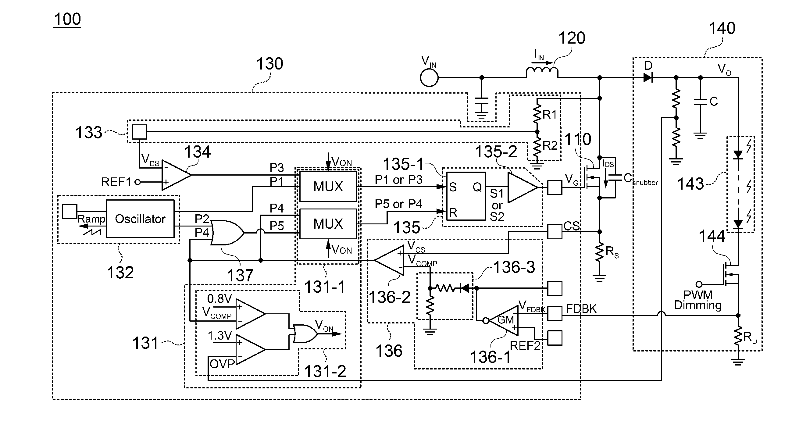
[0052]FIG. 5 is a schematic circuit diagram of a converter 100 according to a first embodiment of the present disclosure.

[0053]The exemplary embodiment of the present disclosure is described in terms of a boost converter, but the present disclosure is not limited thereto. In addition, the converter 100 according to the exemplary embodiment of the present disclosure is configured to supply power to a light emitting diode (LED) string 143 having a plurality of LED devices that are connected in series to each other, but the present disclosure is not limited thereto.

[0054]As illustrated in FIG. 5, the converter 100 according to the exemplary embodiment of the present disclosure may include a switching unit 110, an energy storage unit 120, a switching controller 130, and an output unit 140.

[0055]Although not illustrated, the converter 100 according to the exemplary embodiment of the present disclosure may include a power supplier for rectifying alternating current (AC) input power to gen...

second embodiment

[0161]FIG. 8 is a schematic circuit diagram of a converter 200 according to a second embodiment of the present disclosure.

[0162]The exemplary embodiment of the present disclosure is described in terms of a boost converter, but the present disclosure is not limited thereto. In addition, like in the first embodiment of the present disclosure, the converter 200 according to the exemplary embodiment of the present disclosure is configured to supply power to a light emitting diode (LED) string 243 having a plurality of LED devices that are connected in series to each other, but the present disclosure is not limited thereto.

[0163]As illustrated in FIG. 8, the converter 200 according to the exemplary embodiment of the present disclosure may include a switching unit 210, an energy storage unit 220, a switching controller 230, a detection resistor RS, an output unit 240, etc.

[0164]The switching unit 210, the energy storage unit 220, the detection resistor RS, the output unit 240, etc. accord...


PUM


Abstract

Disclosed herein is a converter including a switching unit, an energy storage unit for storing energy from a direct current (DC) input voltage and then generating an output voltage according to a switching operation of the switching unit, and a switching controller for controlling the switching unit to selectively execute a first operation mode for turning on the switching unit at a fixed frequency or a second operation mode for turning on the switching unit when a voltage between one end and the other end of the switching unit reaches a zero point of a resonance waveform, wherein the switching controller includes an operation mode selection unit for selectively executing the first operation mode or the second operation mode according to whether the voltage between one end and the other end of the switching unit resonates.

Description

CROSS REFERENCE(S) TO RELATED APPLICATIONS[0001]This application claims the foreign priority benefit under 35 U.S.C. Section [120, 119, 119(e)] of Korean Patent Application Serial No. 10-2014-0139693, entitled “Converter” filed on Oct. 16, 2014, which is hereby incorporated by reference in its entirety into this application.BACKGROUND[0002]1. Technical Field[0003]Embodiments of the present invention relates to a converter.[0004]2. Description of the Related Art[0005]In accordance with current trends, in terms of electronic and communication devices, a system part has been rapidly miniaturized and lightweight together with the development of a semiconductor integrated circuit, but a power part has not been miniaturized and lightweight compared with what expected due to an energy storage device such as an inductor, a capacitor, etc.[0006]Accordingly, in order to meet the current trends of miniaturized and lightweight electronic and communication devices, it is very important to obtain...

Claims


Application Information

Patent Timeline
Patent Type & Authority Applications(United States)
IPC IPC(8): H02M3/156
CPCH02M3/156Y02B70/10H02M1/082H02M1/44H02M3/005H03K17/063H03K17/166
Inventor HWANG, BO HYUNLEE, JIN SOOAHN, MIN YOUNGHAN, DAE HOONPARK, JUNG EUI
Owner SKAICHIPS CO LTD
Why Eureka
Try Eureka