Switching power supply unit

a power supply unit and switch technology, applied in the direction of electric variable regulation, process and machine control, instruments, etc., can solve the problems of low reverse withstand voltage, small forward voltage drop of diodes, etc., and achieve the effect of suppressing the surge voltage generated in the rectifier elements and reducing the maximum value of reverse voltag

Active Publication Date: 2007-02-01
TDK CORPARATION
View PDF13 Cites 50 Cited by
  • Summary
  • Abstract
  • Description
  • Claims
  • Application Information

AI Technical Summary

Benefits of technology

[0043] In the third switching power supply unit of an embodiment of the invention, in the time of the forward-direction operation, the first resonance circuit is constructed by the first capacitative element and the first inductor. In the time of the reverse-direction operation, the second resonance circuit is constructed by the first capacitativ

Problems solved by technology

However, the diode having a small forward voltag

Method used


Image

  • Switching power supply unit
  • Switching power supply unit
  • Switching power supply unit

Examples


first embodiment

[0143] A first embodiment of the invention will be described. The first embodiment corresponds to a concrete example of a second switching power supply unit according to the invention.

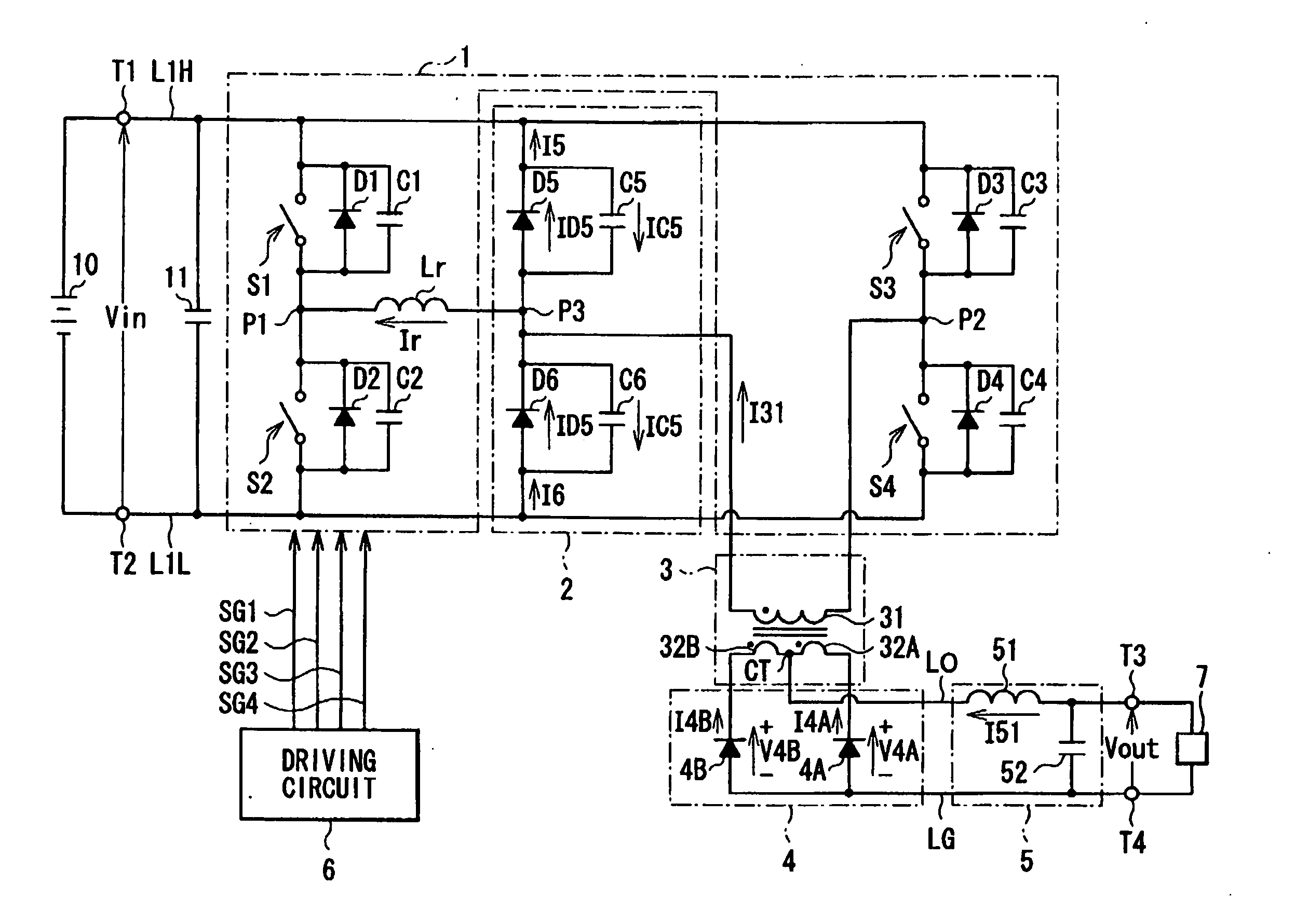
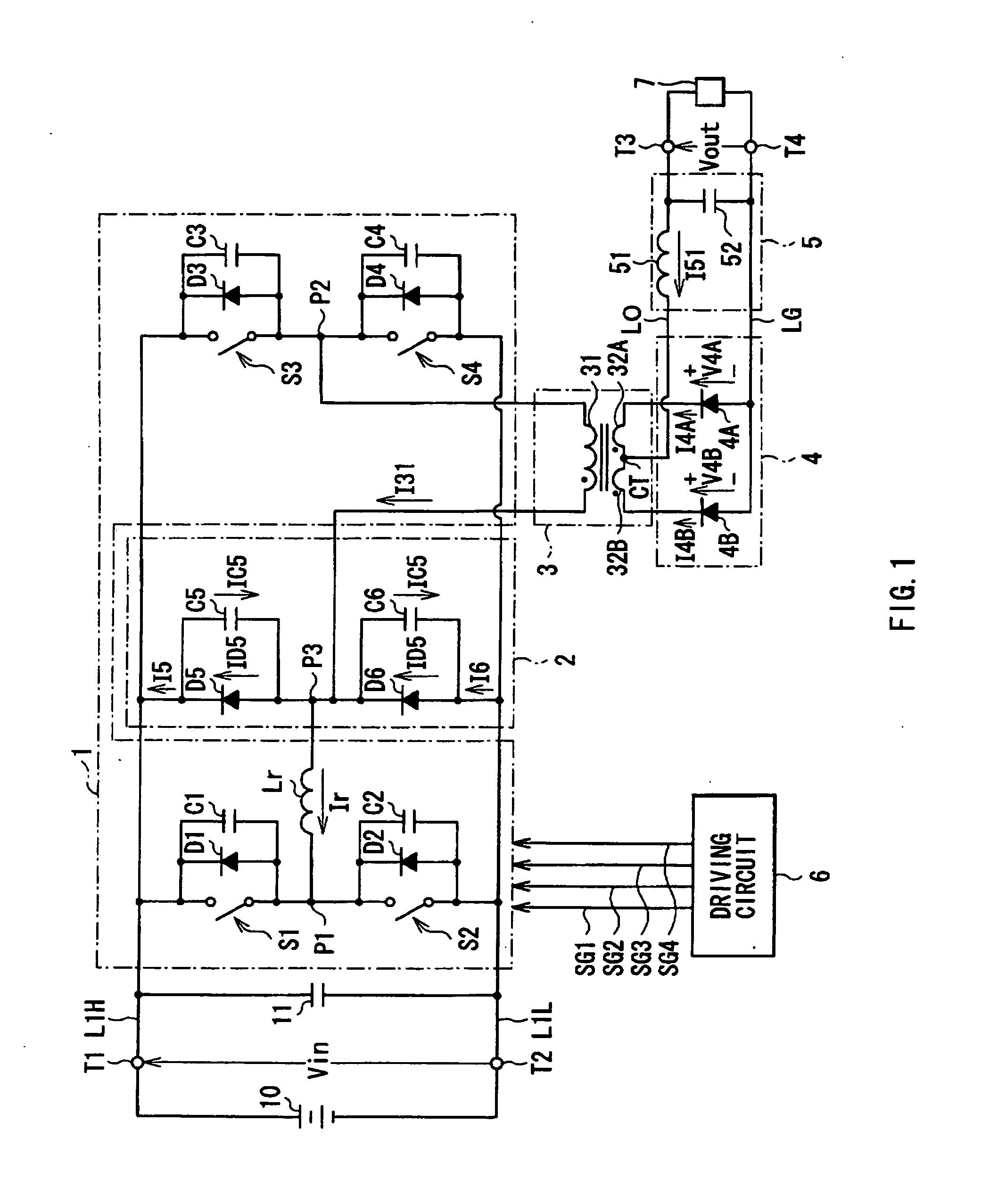
[0144]FIG. 1 shows a configuration of a switching power supply unit according to the first embodiment. The switching power supply unit functions as a DC-DC converter for converting a high DC input voltage Vin supplied from a high-voltage battery 10 to a lower DC output voltage Vout, and supplying the DC output voltage Vout to a not-shown low-voltage battery to drive a load 7.

[0145] The switching power supply unit has an input smoothing capacitor 11, a bridge circuit 1, a surge voltage suppressing circuit 2 which are provided between a primary high-voltage line L1H and a primary low-voltage line L1L, an inductor Lr for resonance, and a transformer 3 having a primary winding 31 and secondary windings 32A and 32B. Across an input terminal T1 of the primary high-voltage line L1H and an input terminal T2 ...

second embodiment

[0209] A second embodiment of the invention will now be described. The second embodiment corresponds to a concrete example of a second switching power supply unit according to the present invention.

[0210]FIG. 29 shows a configuration of a switching power supply unit according to the second embodiment. The switching power supply unit functions as a DC-DC converter for converting a high DC input voltage Vin supplied from the high-voltage battery 10 to a lower DC output voltage Vout, and supplying the DC output voltage Vout to a not-shown low-voltage battery to drive the load 7.

[0211] The switching power supply unit has the input smoothing capacitor 11, a bridge circuit 1001, and a surge voltage suppressing circuit 1002 which are provided between the primary-side high-voltage line L1H and the primary-side low-voltage line L1L, the inductor Lr for resonance, a transformer 1003 having the primary winding 31 and the secondary windings 32A and 32B, a rectifier circuit 1004 provided on th...

third embodiment

[0310] A third embodiment of the present invention will now be described. The third embodiment corresponds to a concrete example of a third switching power supply unit according to the invention.

[0311]FIG. 60 shows the configuration of a switching power supply unit of the third embodiment. The switching power supply unit is a bidirectional switching power supply unit (DC-DC converter). The switching power supply unit can perform: a forward-direction operation of generating a low DC voltage VL on the basis of a high DC voltage VH applied across the input / output terminals T1 and T2 from a high-voltage battery 2051, outputting the low DC voltage VL from the input / output terminals T3 and T4, and supplying it to a low-voltage battery 2052; and an opposite-direction operation for generating the high DC voltage VH on the basis of the low DC voltage VL applied across the input / output terminals T3 and T4 from the low-voltage battery 2052, outputting the high DC voltage VH from the input / out...


PUM


Abstract

The present invention provides a switching power supply unit capable of suppressing a surge voltage generated in a rectifier element more effectively. A first resonance circuit is constructed by capacitors in a surge voltage suppressing circuit and an inductor, and resonance time of the first resonance circuit is set to be longer than recovery time of a diode in a rectifier circuit. According to at least one of a DC input voltage and an output current, either a first bridge circuit or a second bridge circuit is selectively allowed to perform switching operation. At the time of forward-direction operation, the first resonance circuit is formed by the capacitors in the surge voltage circuit and the inductor on the high voltage side. At the time of reverse-direction operation, a second resonance circuit is formed by the capacitors and an inductor on the low voltage side.

Description

BACKGROUND OF THE INVENTION [0001] 1. Field of the Invention [0002] The present invention relates to a switching power supply unit for connecting an output obtained by switching a direct current input voltage to an output winding of a power converting transformer. [0003] 2. Description of the Related Art [0004] Hitherto, various types of switching power supply units have been proposed and provided for practical use. Many of them are of a type in which a direct current input voltage is switched by switching operation of a switch circuit connected to an input winding of a power converting transformer, and the switched output is connected to an output winding of the power converting transformer. A voltage appearing in the output winding in association with such switching operation of the switch circuit is rectified by a rectifier circuit, the rectified voltage is converted to a direct current voltage by a smoothing circuit, and the smoothed voltage is output. [0005] In a switching powe...

Claims


Application Information

Patent Timeline
IPC IPC(8): H02H7/122
CPCH02M1/32H02M1/34Y02B70/1491H02M2001/342H02M3/3376H02M3/33584H02M3/3378Y02B70/10H02M1/0058H02M1/342
Inventor NAKAHORI, WATARUMURAI, YASUHIRO
Owner TDK CORPARATION
Why Eureka
Try Eureka