Process for forming a sleeve on a container

Inactive Publication Date: 2016-04-28
THE PROCTER & GAMBLE COMPANY
View PDF0 Cites 4 Cited by
  • Summary
  • Abstract
  • Description
  • Claims
  • Application Information

AI Technical Summary

Problems solved by technology

A problem with this approach is that there are technical difficulties with precisely registering the shrink sleeve with the container so that the pre-cut hole, when shrunk, is located as desired, particularly for high speed packaging lines.
Further, as the shrink sleeve is shrunk, the hole can tend to become uncontrollably irregularly shaped as tension develops in the shrink sleeve.
For containers having a grip, such as an indention, pair of indentions, or through handle, a pre-cut hole in a shrink sleeve that is poorly registered with such feature can result in a grip that has decreased functionality.
The decrease in functionality can arise as a result of portions of the shrink sleeve adjacent the cut-out covering portions of the container that the package designer desires the consumer to be able to contact directly.
Such an arrangement can result in the consumer having to form part of her grip on t

Method used


Image

  • Process for forming a sleeve on a container
  • Process for forming a sleeve on a container
  • Process for forming a sleeve on a container

Examples


Embodiment Construction

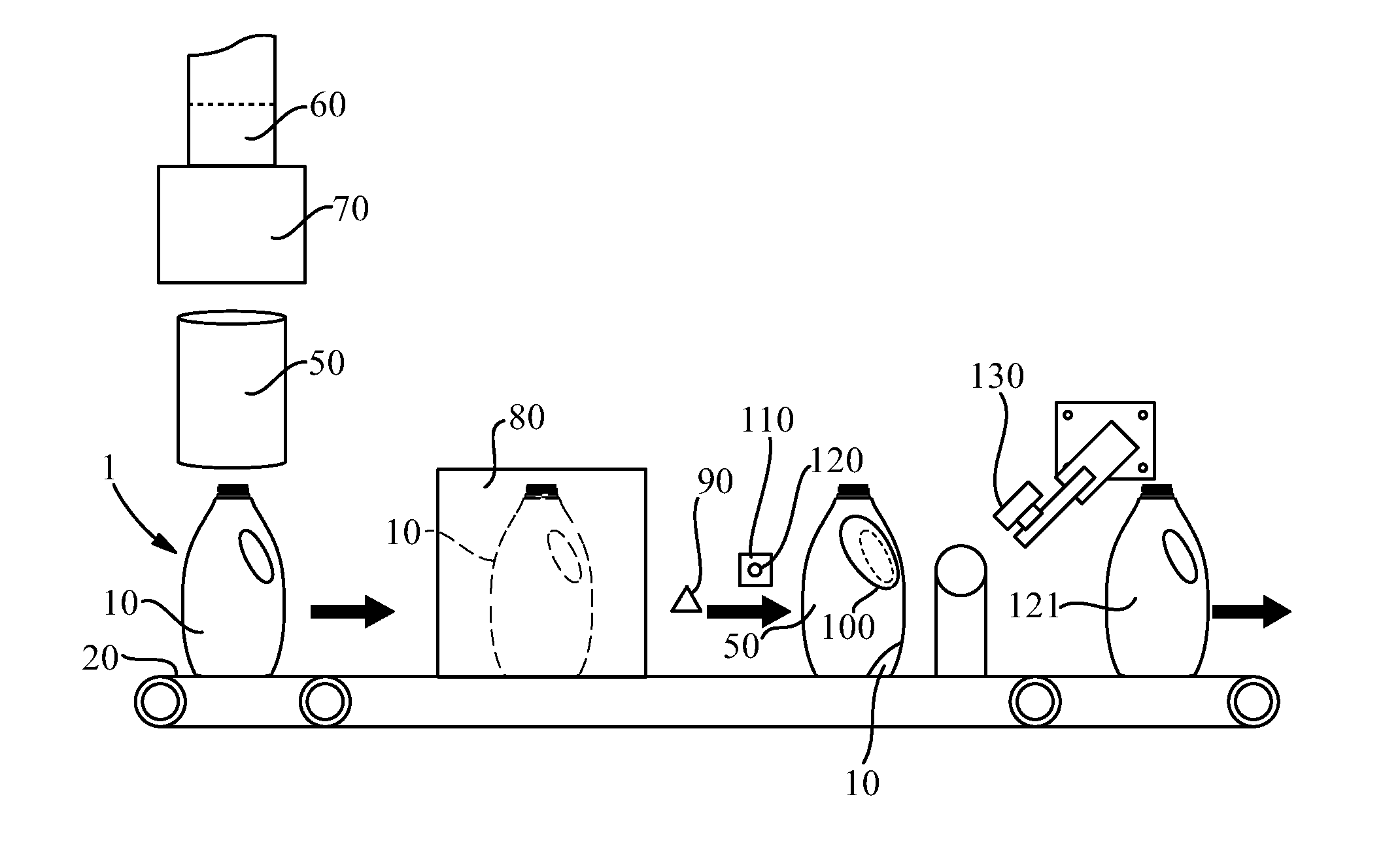
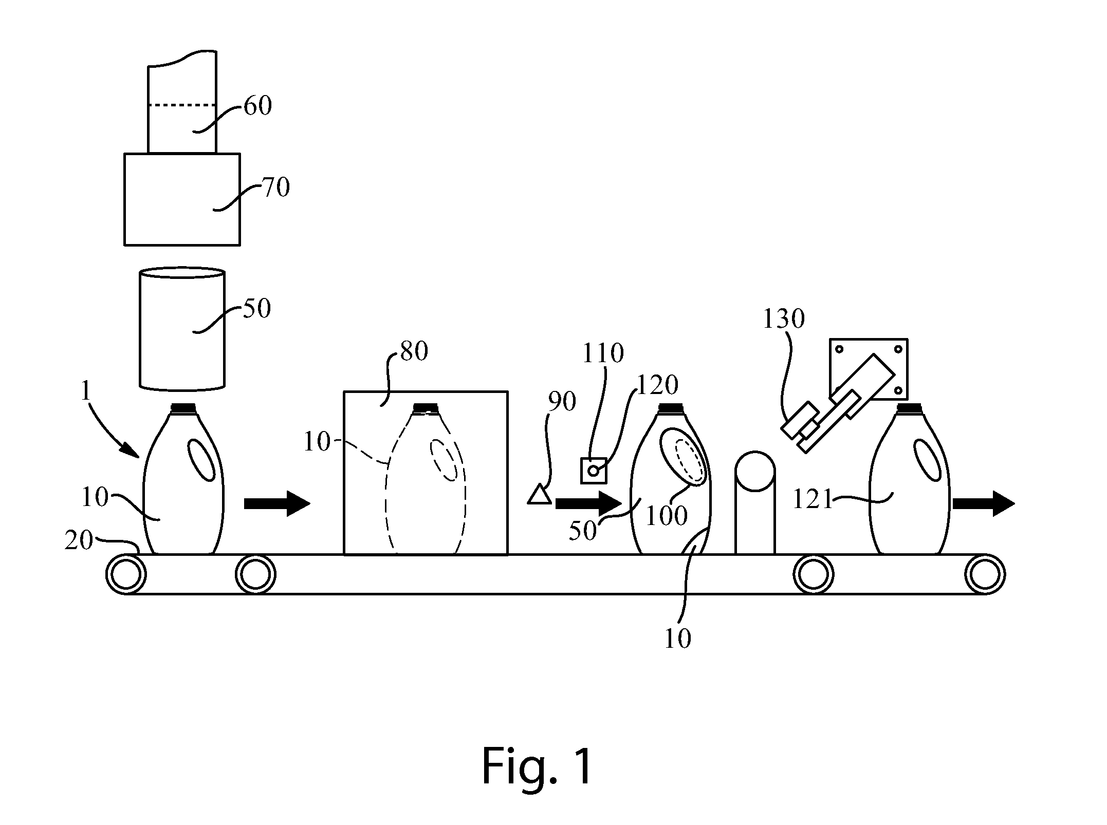
[0017]A shrink sleeving line 1 is shown in FIG. 1. The shrink sleeving line 1 can comprise a conveyor 20. A container 10 can be provided on a conveyor 20. A shrink sleeve 50 can be applied to the container before or after filling and or capping of the container. Most commonly, a shrink sleeve 50 is applied to the container prior to filling and capping. The container 10 can be filled by a filling device before or after the container 10 arrives at the sleeve handling device 70 and heating zone 80. The container can be filled with a composition. Exemplary compositions can include powders, granules, liquids, and gels. The composition can be liquid laundry detergent, liquid shampoo, household cleaning product, powder laundry detergent, liquid soap, liquid dish detergent, liquid bleach, liquid fabric treatment composition, liquid food product, or any other material that can be dispensed into a container 10 for subsequent use or dispensing by a person.

[0018]A shrink sleeve 50 is applied to...


PUM

PropertyMeasurementUnit
Fractionaaaaaaaaaa
Fractionaaaaaaaaaa
Shrinkageaaaaaaaaaa

Abstract

A process for forming a sleeve on a container including the steps of: providing a container; placing a shrink sleeve around the container; conforming the shrink sleeve to the container by shrinking the shrink sleeve; providing a predetermined removeable portion in the shrink sleeve; providing a striker moving tangentially relative to the predetermined removeable portion; and removing the predetermined removeable portion by contacting the striker to the predetermined removeable portion.

Description

FIELD OF THE INVENTION[0001]Forming a shrink sleeve on a container.BACKGROUND OF THE INVENTION[0002]Shrink sleeve labels are widely used for decorating containers. Shrink sleeve labels provide several advantages over other labeling and decoration techniques including the ability to decorate the entire peripheral wall of irregularly shaped packages, the ability to generate a variety of visually distinct packages using a single container shape, and the ability make rapid changes to artwork for packages.[0003]For some packages, designers desire to have an opening in the shrink sleeve to provide a window through which the underlying container and or contents of the container are visible or to provide a location to grip the package. Openings can be provided in shrink sleeves by including a pre-cut hole in the shrink sleeve prior to the shrink sleeve being placed over the container and subsequently shrunk. A problem with this approach is that there are technical difficulties with precisel...

Claims


Application Information

Patent Timeline
IPC IPC(8): B29C65/00B32B38/00B32B37/14
CPCB29C66/73715B32B37/144B29C66/0326B32B2439/00B29L2031/712B32B2307/50B32B38/0004B29C63/423B65C3/065B29L2031/7158
Inventor GOUDY, ERIC SHAWN
Owner THE PROCTER & GAMBLE COMPANY
Why Eureka
Try Eureka