Pluggable optical transceiver
- Summary
- Abstract
- Description
- Claims
- Application Information
AI Technical Summary
Benefits of technology
Problems solved by technology
Method used
Image
Examples
first embodiment
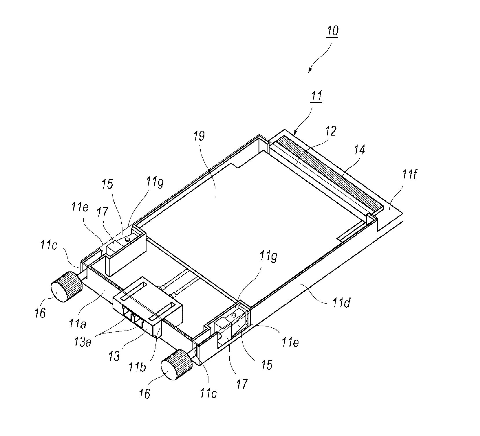
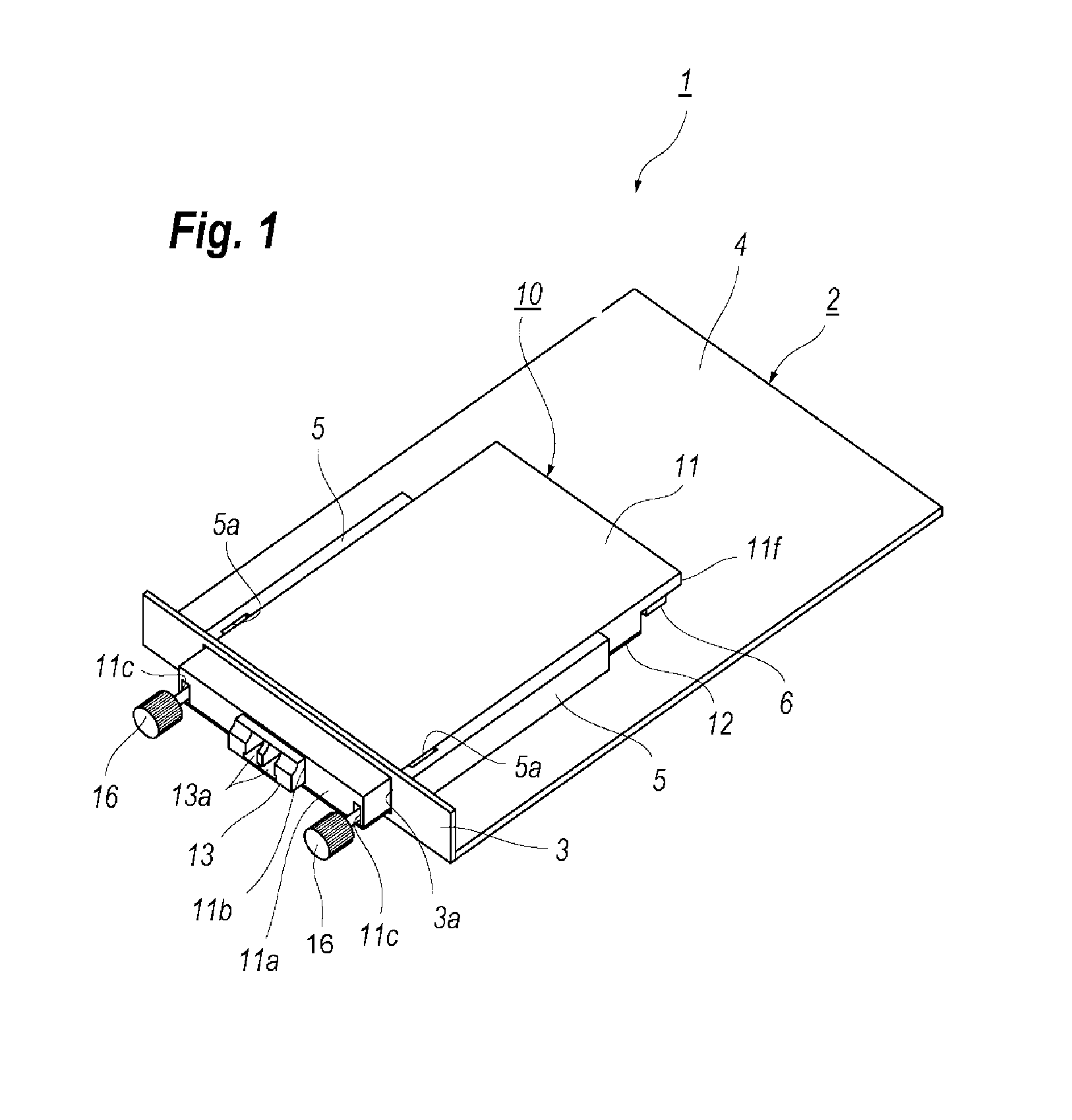
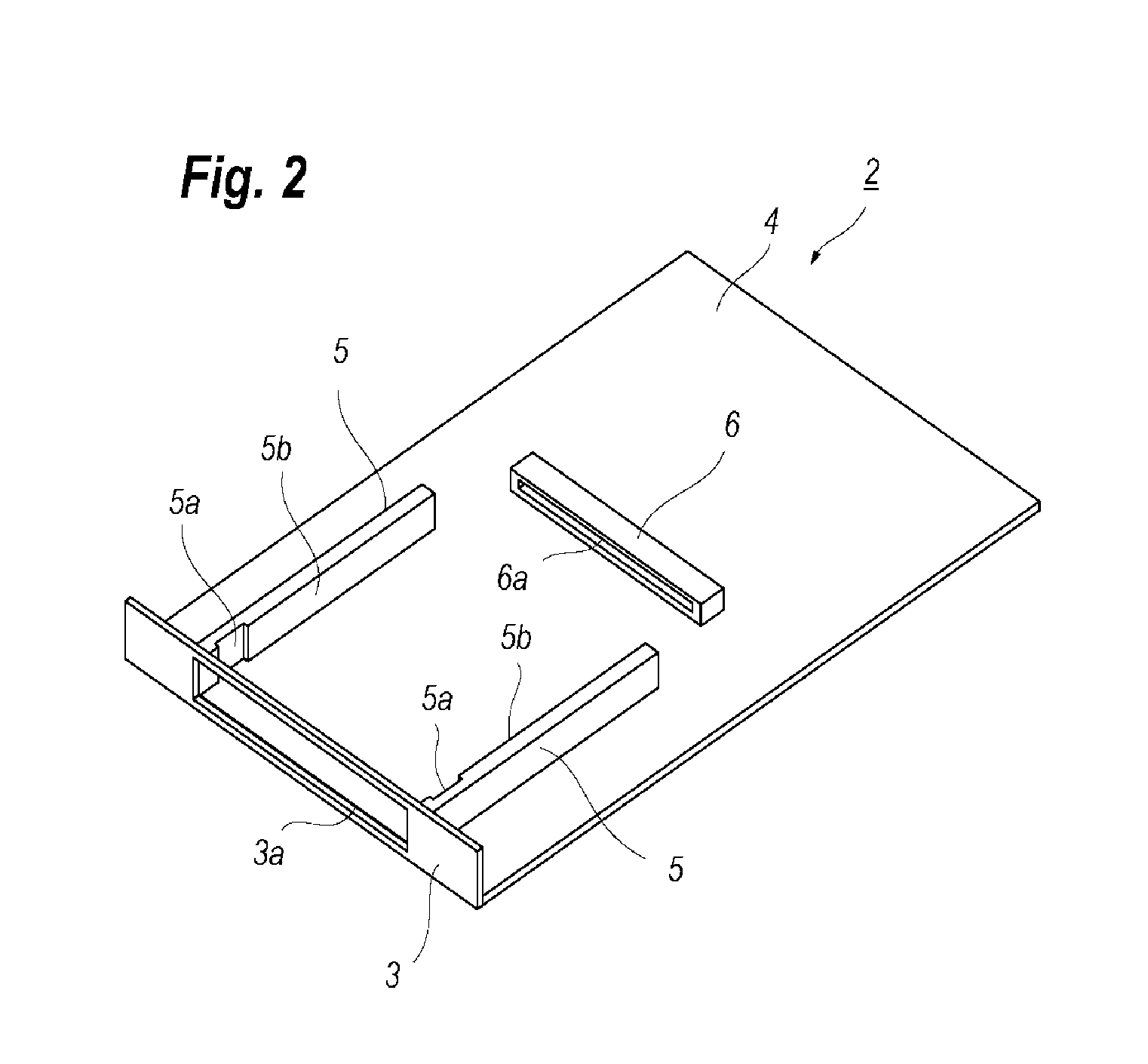
[0025]FIG. 1 is a perspective view showing a transceiver system where an optical transceiver is set on a host system 2. The transceiver system 1 includes a host system 2 and a pluggable optical transceiver 10 of a type of CFP (Centum gigabit Form Factor Pluggable), which follows one of MSAs (multi-source agreements) concerning to optical transceivers; FIG. 2 is a perspective view showing only the host system 2; and FIG. 3 is also a perspective view showing only the optical transceiver 10.
[0026]Referring to FIG. 2, the host system. 2 includes a front panel 3, a circuit board 4, two rails 5, and a host connector 6. Referring to FIG. 3, the optical transceiver 10 includes a top housing 11, a bottom housing 12, an optical receptacle 13, an electrical plug 14, actuators 15, fastening screws 16, holders 17, a circuit board 19, and coil springs 20, where the actuators 15, the holders 17, the fastening screws 16, and the coil springs 20 are provided in respective sides of the optical transc...
second embodiment
[0048]Next, an optical transceiver according to another embodiment of the present application will be described as referring to FIGS. 11 to 13B, where FIG. 11 is a perspective view of a CFP transceiver, FIG. 12 magnifies the screw, the actuator, and the holder of the second embodiment, and FIGS. 13A and 13B show a mechanism to engage the CFP transceiver with the host system. The optical transceiver 30 of the present embodiment provides a leaf spring 31, an actuator 35, a holder 37, a top housing 41, and a bottom housing 42, where FIG. 11 omits a part of members for an explanation's sake.
[0049]The top housing 41 provides a groove 41j extending longitudinally in the side of the top housing 41. Although not shown in figures, the bottom housing 42 also provides a groove corresponding to the groove 41j in the top housing 41. The actuator 35 of the present embodiment has a block shape with two outer surfaces, 35a and 35b, protruding from the window 11e of the top housing 11. Inserting the...
third embodiment
[0053]FIG. 14 is a perspective view of a CFP transceiver 50 according to the third embodiment of the present application, and FIG. 15 magnifies a portion of the pocket 11g of the top housing 51 where the fastening screw 16 and the actuator 55 are set therein. The optical transceiver 50 of the third embodiment provides the top housing 51 that includes an spring 61, a screw hole 51a, the actuator 55 with a slab shape, a pusher 54 set in front of the spring 61, and a block 56 set between the actuator 55 and the end 16a of the fastening tool 16.
[0054]Referring to FIG. 15, the top housing 51 provides a wall 51b that partitions the pocket 11g from the guide 11c. The wall 51b provides the screw hole 51a so as to pierce the wall 51b. The end 16a of the fastening screw 16 passes through the screw hole 51a and abuts against the block 56 set behind the wall 51b. The top housing 51 also provides a side wall 51c to partition the pocket 11g from the outside.
[0055]The pocket 11g sets the spring 61...
PUM
 Abstract
Description
Claims
Application Information
 - R&D
- Intellectual Property
- Life Sciences
- Materials
- Tech Scout
- Unparalleled Data Quality
- Higher Quality Content
- 60% Fewer Hallucinations
Browse by: Latest US Patents, China's latest patents, Technical Efficacy Thesaurus, Application Domain, Technology Topic, Popular Technical Reports.
© 2025 PatSnap. All rights reserved.Legal|Privacy policy|Modern Slavery Act Transparency Statement|Sitemap|About US| Contact US: help@patsnap.com


