Battery terminal

a battery terminal and battery technology, applied in the field of battery terminals, can solve problems such as difficult work using fitting tools, and achieve the effect of reducing work spa

Active Publication Date: 2016-05-05
YAZAKI CORP
View PDF1 Cites 7 Cited by
  • Summary
  • Abstract
  • Description
  • Claims
  • Application Information

AI Technical Summary

Benefits of technology

[0009]The present invention has been made in consideration of the foregoing, and an object of the present invention is to provide a battery terminal capable of reducing the work space required in the periphery of the battery when fastened to the battery post.

Problems solved by technology

Hence, it has been necessary to take up a large work space to insert and operate the tool on the lateral side of the battery.
Thus, conceivable is a situation in which, when the conventional battery terminal of the lateral tightening method is used, the work using a fitting tool is difficult.

Method used


Image

  • Battery terminal
  • Battery terminal
  • Battery terminal

Examples


first embodiment

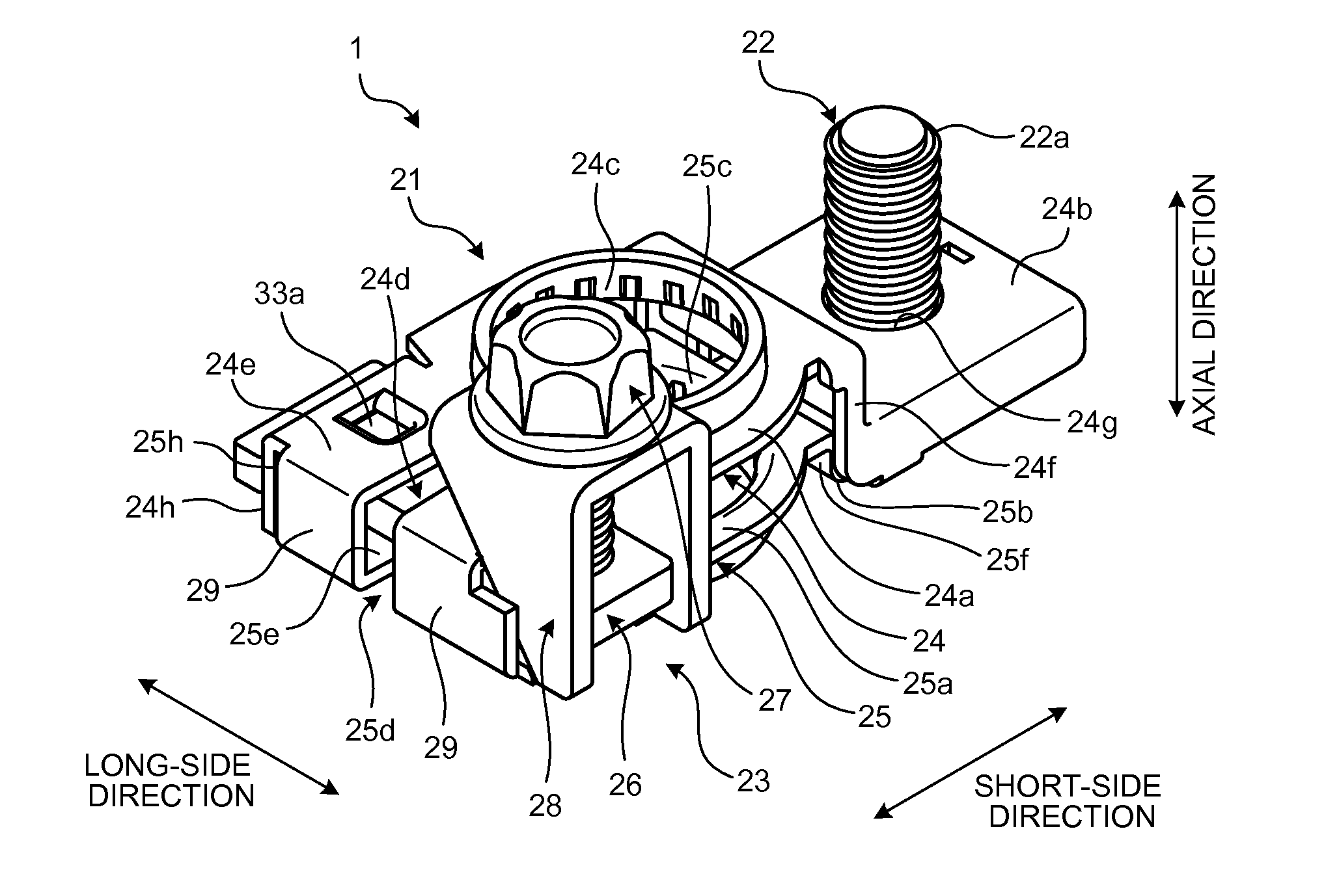
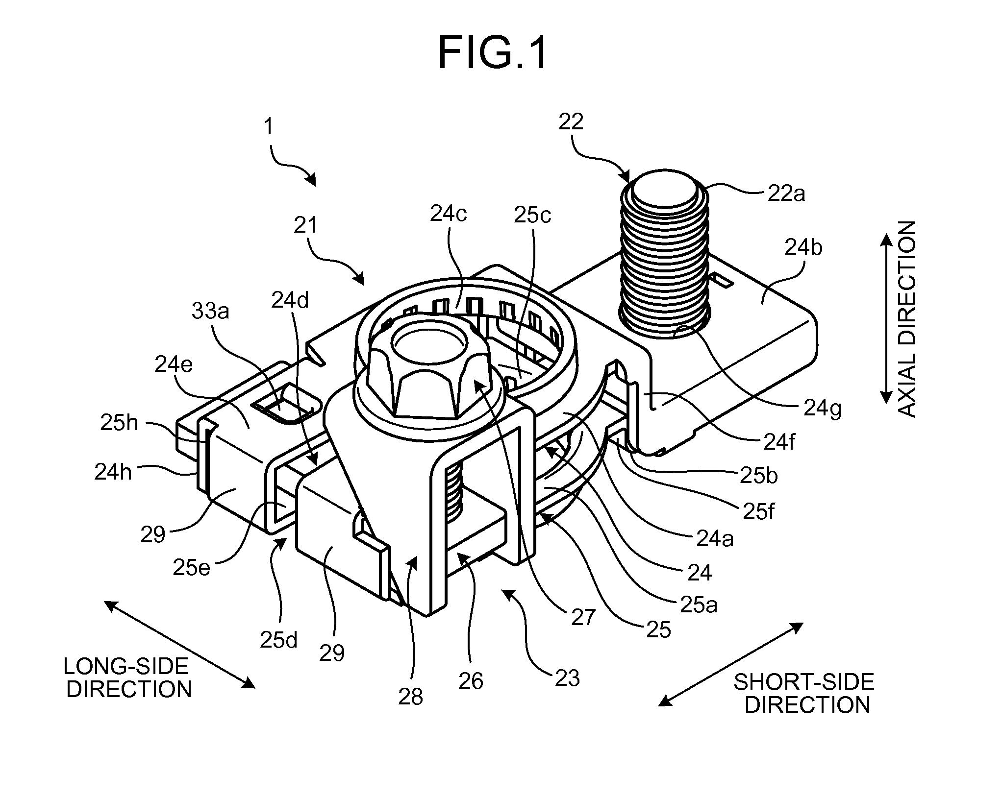
[0031]FIG. 1 is a perspective view schematically illustrating the configuration of a battery terminal according to a first embodiment of the present invention. FIG. 2 is an exploded perspective view of the battery terminal illustrated in FIG. 1. FIG. 3 is a perspective view illustrating a state in which the battery terminal illustrated in FIG. 1 is mounted on a battery post. FIG. 4 is a plan view illustrating the state in which the battery terminal illustrated in FIG. 1 is mounted on the battery post. FIG. 5 is a sectional view viewed along the V-V line in FIG. 3.

[0032]A battery terminal 1 in the first embodiment is, as illustrated in FIGS. 3 and 4, fitted to a battery post 51 of a battery 50. The battery terminal 1 is a component to electrically connect, by being mounted on the battery post 51, the battery 50 with a metal fitting and the like that is provided at the end portion of an electrical wire on the main body side of a vehicle and the like in which the battery 50 is installe...

second embodiment

[0082]FIG. 8 is a perspective view schematically illustrating the configuration of a battery terminal according to a second embodiment of the invention. FIG. 9 is an exploded perspective view of the battery terminal illustrated in FIG. 8. FIG. 10 is a plan view illustrating the state in which the battery terminal illustrated in FIG. 8 is mounted on the battery post. FIG. 11 is a diagram viewed from the arrow direction L1 in FIG. 10.

[0083]A battery terminal 101 in the second embodiment is, as illustrated in FIGS. 10 and 11, fitted to a battery post 151 of a battery 150. The battery terminal 101 is a component to electrically connect, by being mounted on the battery post 151, the battery 150 with a metal fitting and the like that is provided at the end portion of an electrical wire on the main body side of a vehicle and the like in which the battery 150 is installed.

[0084]In the following description, the direction along the central axis line X of the battery post 151 is referred to a...


PUM

PropertyMeasurementUnit
widthaaaaaaaaaa
tightening forceaaaaaaaaaa
sizeaaaaaaaaaa

Abstract

A battery terminal includes a penetration plate arranged to penetrate from one end portions of annular portions to the other end portions interposing slits, a fastening bolt supported to be rotatable around an axial direction by a threaded hole provided on the other end portion of the penetration plate, and a spacer arranged in contact with the annular portions from the other end portion side of the penetration plate and converting a tightening force in the axial direction arising along with the rotation of the fastening bolt around the axial direction into a pressing force that presses the annular portions from a long-side direction. The penetration plate is arranged to penetrate a clearance of the pair of annular portions. The pair of annular portions includes projecting portions as a clearance reduction portion that reduces the clearance in at least a part of the penetration area of the penetration plate.

Description

CROSS-REFERENCE TO RELATED APPLICATION(S)[0001]The present application claims priority to and incorporates by reference the entire contents of Japanese Patent Application No. 2014-224556 filed in Japan on Nov. 4, 2014 and Japanese Patent Application No. 2015-025635 filed in Japan on Feb. 12, 2015.BACKGROUND OF THE INVENTION[0002]1. Field of the Invention[0003]The present invention relates to a battery terminal.[0004]2. Description of the Related Art[0005]Conventionally, a battery terminal to be mounted on a battery post that is provided to stand on a battery installed in a vehicle and the like has been known. As a conventional battery terminal, Japanese Patent Application Laid-open No. H09-245767 discloses the configuration of a battery terminal that can be mounted on a battery post by being fastened while the battery post is inserted to a through-hole thereof, for example. As described in Japanese Patent Application Laid-open No. H09-245767, in general, the conventional battery ter...

Claims


Application Information

Patent Timeline
Patent Type & Authority Applications(United States)
IPC IPC(8): H01M2/30H01M50/50H01M50/552H01M50/567
CPCH01M2220/20H01M2/305H01M50/567H01M50/552H01M50/50H01R11/283Y02E60/10H01M50/561
Inventor KATO, TAKAYUKISHIOHAMA, TAKAHIROYOSHIDA, TAKASHI
Owner YAZAKI CORP
Why Eureka
Try Eureka