Video laryngoscope

a laryngoscope and video technology, applied in the field of laryngoscopes, can solve the problems of respiratory failure, inability to access images, and lack of self-protection of respiratory tracks

Inactive Publication Date: 2016-05-12
LAI HSIEN YUNG
View PDF5 Cites 8 Cited by
  • Summary
  • Abstract
  • Description
  • Claims
  • Application Information

AI Technical Summary

Benefits of technology

[0014]Since the electrical signals transformed from the images obtained by the lens 130 will be output to the smart communication device 160 the smart communication device 160 can be used to display the images of the lens 130 to achieve the function of the video laryngoscope 100. Moreover, these images also can be stored in the smart communication device 160 when needed, and can be used by physicians or hospital for subsequent records or edit. Furthermore, in teaching, teachers only need to use the smart communication device 160 to transfer the images to students, and then the students can display the images through their own electronic devices. Therefore, a large group of people huddled together to see teacher's demonstration is not needed.

Problems solved by technology

Common causes of intubation include respiratory failure and respiratory track having no self-protection.
However, most of the present video laryngoscope can only display images on screen, but cannot access the images.
Hence, the images cannot be edited, copied, or transferred.
Accordingly, the video laryngoscopes still have limitations in applications to be solved.

Method used


Image

  • Video laryngoscope
  • Video laryngoscope
  • Video laryngoscope

Examples


Embodiment Construction

[0012]In the following detailed description, for purposes of explanation, numerous specific details are set forth in order to provide a thorough understanding of the disclosed embodiments. It will be apparent, however, that one or more embodiments may be practiced without these specific details. in other instances, well-known structures and devices are schematically shown in order to simplify the drawing.

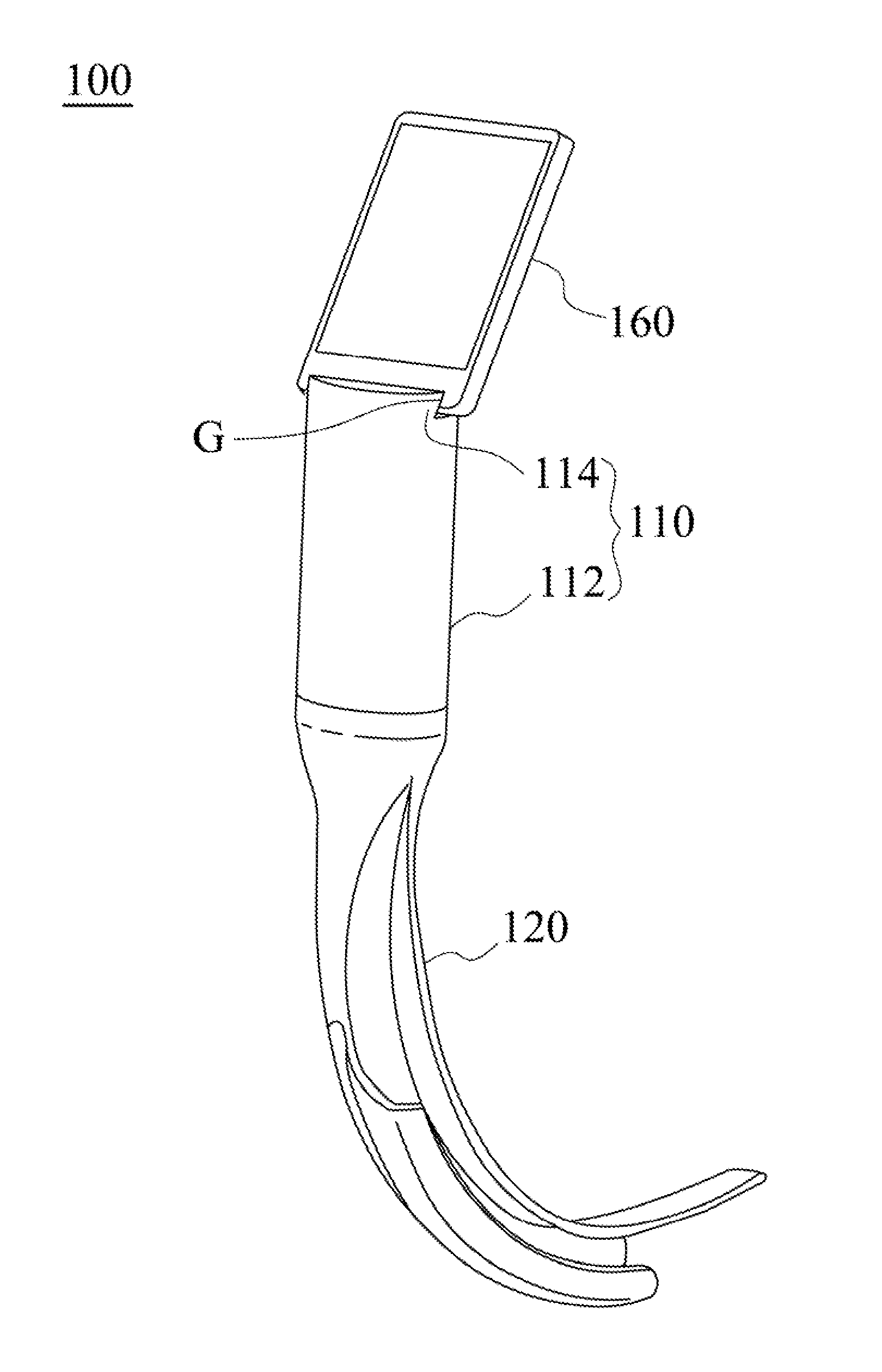
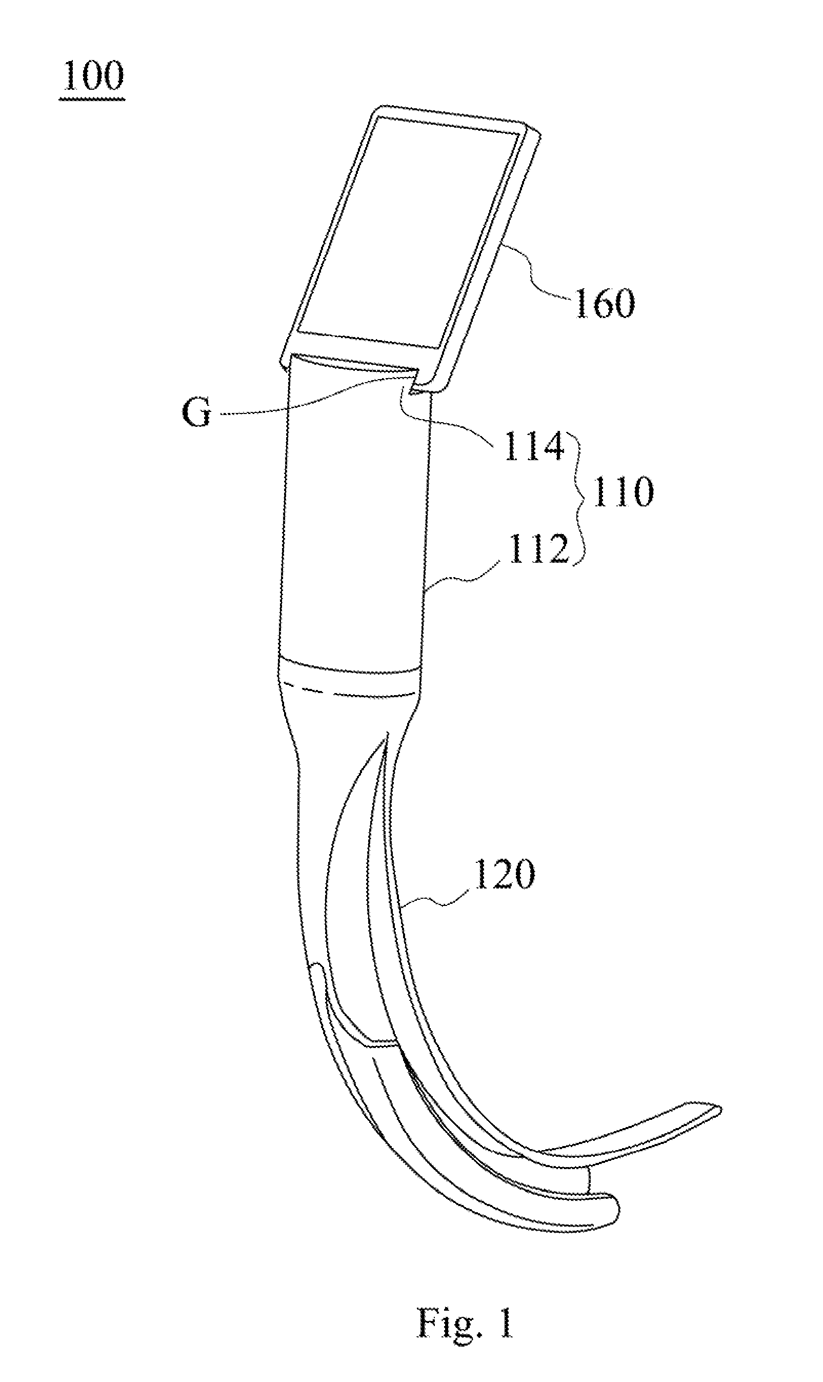
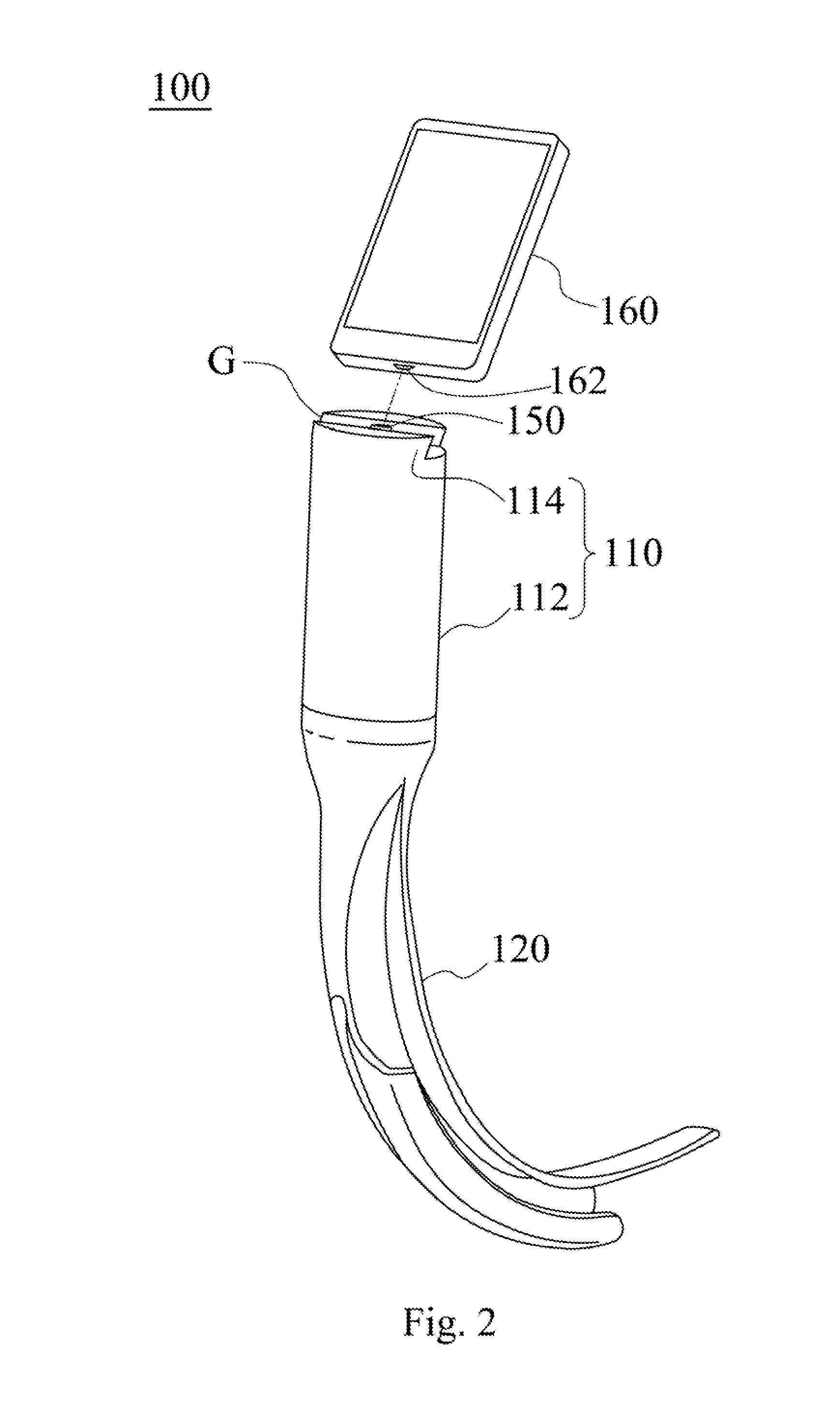
[0013]FIG. 1 is a perspective view of a video laryngoscope 100 according to some embodiments of the present disclosure. FIG. 2 is an exploded view of the video laryngoscope 100 in FIG. 1. FIG. 3 is a functional block diagram of the video laryngoscope 100 in FIG. 1. As shown in FIGS. 1-3, a video laryngoscope 100 includes a handle 110, a blade 120, a lens 130, a photo sensor 140, and an output terminal 150. The blade 120 is connected to the handle 110. The lens 130 is disposed on the blade 120. The photo sensor 140 is connected to the lens 130 to transform an image obtained by the le...


PUM


Abstract

A video laryngoscope includes a handle, a blade, a lens, a photo sensor, and an output terminal. The blade is connected to the handle. The lens is disposed on the blade. The photo sensor is connected to the lens to transform an image obtained by the lens into an electrical signal. The output terminal is disposed on the handle and is electrically connected to the photo sensor. The output terminal is configured to allow a smart communication device to be connected thereto, such that the electrical signal can be output to the smart communication device through the output terminal.

Description

CROSS-REFERENCE TO RELATED APPLICATION[0001]This application claims the priority benefit of Taiwanese application serial no. 103139267, filed Nov. 12, 2014, the full disclosure of which is incorporated herein by reference.BACKGROUND[0002]1. Technical Field[0003]This disclosure relates to laryngoscopes. More particularly, the disclosure relates to video laryngoscopes.[0004]2. Description of Related Art[0005]Endotracheal intubation is inserting an endotracheal tube from a mouth or a nasal cavity, through the throat and the glottis, and into the trachea, whereby an artificial open airway is established. Common causes of intubation include respiratory failure and respiratory track having no self-protection. In early times, endotracheal intubation is performed by fingers groping. Latter, direct laryngoscope began to be widely used. Recently, videos through optical fibers were added into the direct laryngoscopes to become video laryngoscopes. This technology improves the past problem of d...

Claims


Application Information

Patent Timeline
Patent Type & Authority Applications(United States)
IPC IPC(8): A61B1/267A61B1/00A61B5/00A61B1/05
CPCA61B1/267A61B1/051A61B5/6898A61B1/00165A61B1/00124A61B1/00048A61B1/00052
Inventor LAI, HSIEN-YUNG
Owner LAI HSIEN YUNG
Why Eureka
Try Eureka