Laryngoscopes, laryngoscope arms and methods of manufacture

a technology of laryngoscopes and laryngoscopes, which is applied in the field of laryngoscopes, can solve the problems of difficult to adequately sterilize such laryngoscopes after use without fully disassembling, difficult to clean spaces, and gaps when they are assembled, so as to minimise the number of features, easy to clean or sterilize, and simple and cost-effective manufacturing methods

Active Publication Date: 2016-04-19
COVIDIEN AG
View PDF14 Cites 4 Cited by
  • Summary
  • Abstract
  • Description
  • Claims
  • Application Information

AI Technical Summary

Benefits of technology

[0015]Providing a laryngoscope arm overmoulded to provide a smooth outer surface has the benefit of allowing the laryngoscope arm to be readily cleaned or sterilised, and minimises the number of features, such as seams or joints, where dirt or infectious bodies may be retained. The overmoulding typically forms the outside surface of the majority or all of the laryngoscope arm. The overmoulding typically has a smooth outer skin, providing structural integrity, avoiding features which may retain dirt and providing comprehensive sealing.
[0055]The elongate conductor retaining member may be tubular. The step of forming the elongate conductor retaining member may comprise the step of blow moulding a metal tube. A tubular elongate conductor retaining member facilitates the threading of one or more electrical conductors after the step of overmoulding.

Problems solved by technology

Laryngoscopes typically comprise at least two parts, resulting in gaps and joins when they are assembled.
Microbes may collect and proliferate in such spaces and such spaces may be hard to clean.
Therefore, it may be difficult to adequately sterilise such laryngoscopes after use without fully disassembling them.
Furthermore, the more locations on the surface of a laryngoscope or part of a laryngoscope, such as a laryngoscope arm, in which microbes may aggregate, the harder it will be to adequately sterilise the laryngoscope or part of the laryngoscope.
As discussed above, it may be harder to adequately sterilise laryngoscopes comprising at least two parts.
However, the bulkier the blade, the more difficult it will be obtain a clear view of the larynx or to manoeuvre the blade and the greater the chance of damaging the patient's teeth.

Method used


Image

  • Laryngoscopes, laryngoscope arms and methods of manufacture
  • Laryngoscopes, laryngoscope arms and methods of manufacture
  • Laryngoscopes, laryngoscope arms and methods of manufacture

Examples


Embodiment Construction

. AN EXAMPLE EMBODIMENT

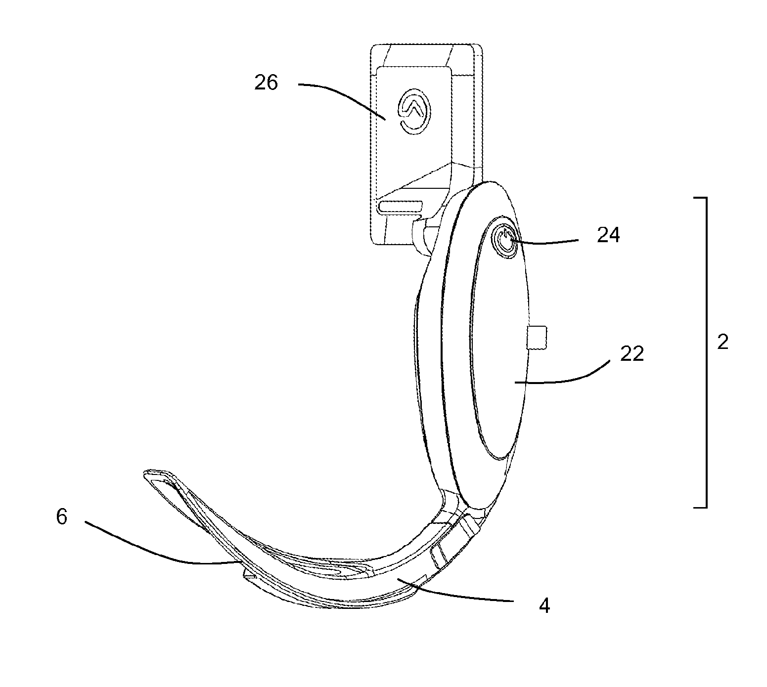
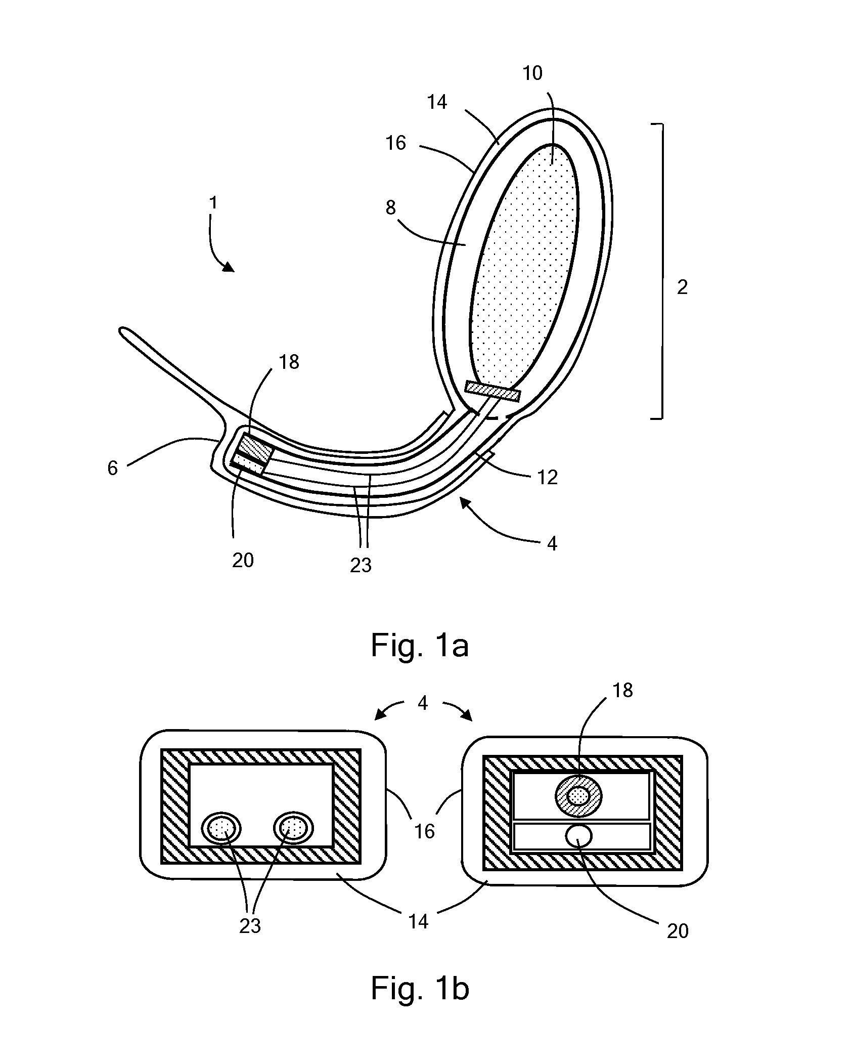
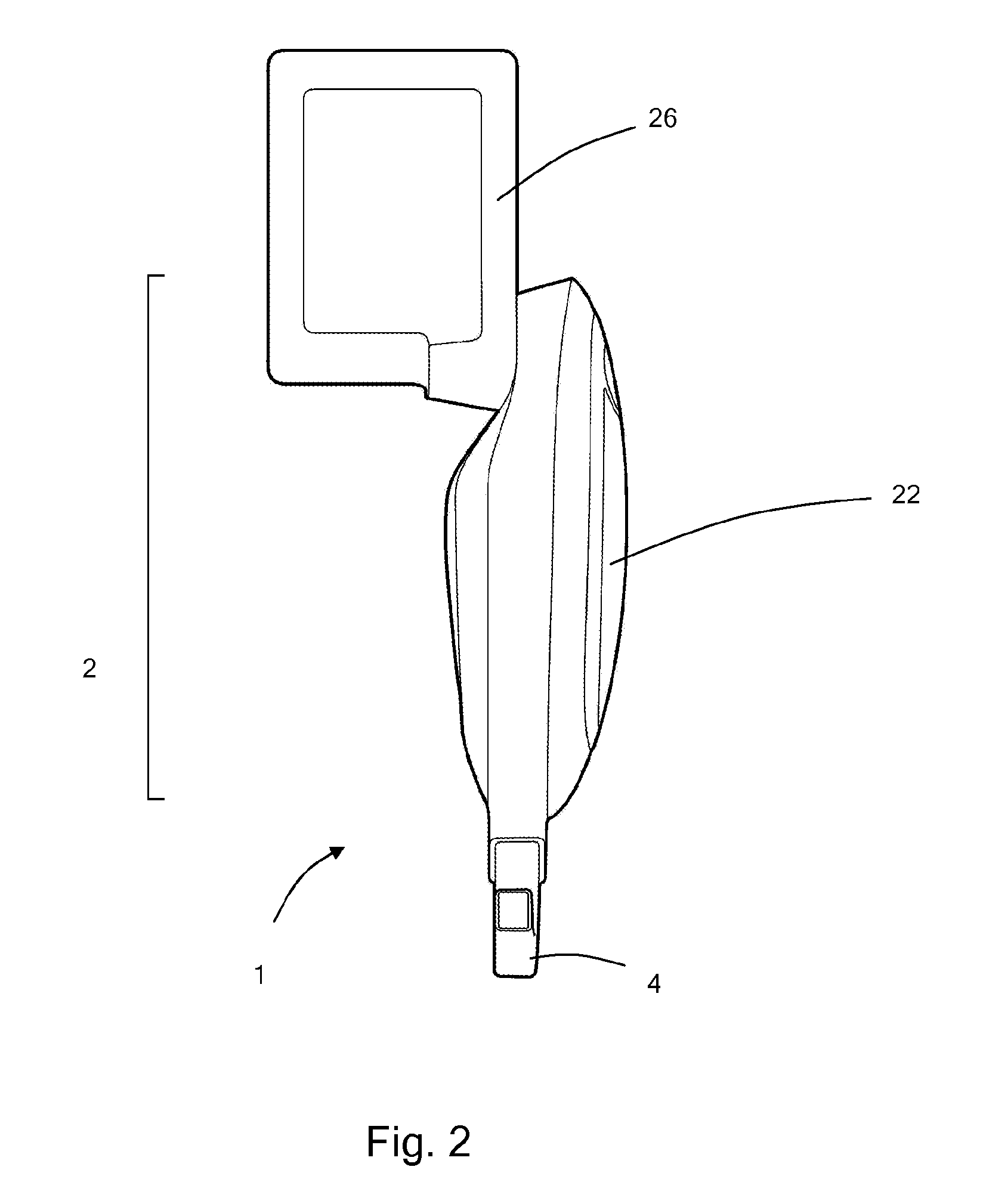
[0088]With reference to FIGS. 1 to 3 a video laryngoscope 1 comprises a body 2 and an arm 4. The video laryngoscope is typically used with a demountable transparent rigid plastics sheath 6, functioning as a laryngoscope blade.

[0089]The laryngoscope comprises a chassis formed by a metal loop 8 within the body, which has a central aperture providing a space for electronics 10, batteries and so forth, and a metal tube 12 which extends from the metal loop. The metal loop functions as a strengthening element for the body and the metal tube functions as a strengthening element for the arm.

[0090]The chassis is covered with an overmould 14 of a plastics material. The overmould has a smooth outer surface 16. In this example, the overmould is continuous over both the handle and arm, however, this may not be the case.

[0091]The arm also includes a video camera 18 and a light 20 (typically and LED), which may be attached to the end of the overmould, behind a suitable trans...


PUM

PropertyMeasurementUnit
forceaaaaaaaaaa
electricalaaaaaaaaaa
force vectoraaaaaaaaaa

Abstract

A video laryngoscope has an arm comprising a video camera, at least one electrical conductor extending to the video camera, an elongate electrical conductor retaining member retaining the electrical conductor and an overmolding extending around the elongate cable retaining member and having a smooth outer surface. Providing a laryngoscope arm overmolded to provide a smooth outer surface has the benefit of allowing the laryngoscope arm to be readily cleaned or sterilized, and minimizes the number of features, such as seams or joints, where dirt or infectious bodies may be retained.

Description

[0001]This application is the U.S. national phase of International Application No. PCT / GB2011 / 050922 filed 13 May 2011 which designated the U.S. and claims priority to GB Patent Application Nos. 1008021.6 filed 13 May 2010 and 1017291.4 filed Oct. 13, 2010, the entire contents of each of which are hereby incorporated by reference.FIELD OF THE INVENTION[0002]The present invention relates to the field of laryngoscopes, including video laryngoscopes, and in particular to the field of laryngoscope arms, and methods of manufacturing laryngoscope arms.BACKGROUND TO THE INVENTION[0003]Laryngoscopes are medical devices which are employed to introduce endotracheal tubes into patient's airways, for example, when a patient is being anaesthetised.[0004]Laryngoscopes comprise handles and arms. Within the specification, the term laryngoscope arm is used to refer to the part of the laryngoscope which extends from the handle into the patient's mouth in use.[0005]Laryngoscope handles are usually elo...

Claims


Application Information

Patent Timeline
Patent Type & Authority Patents(United States)
IPC IPC(8): A61B1/267A61B1/00
CPCA61B1/267A61B1/00052A61B1/00066A61B1/00078Y10T29/49002A61B1/044A61B1/00124
Inventor MCGRATH, MATTHEW JOHN ROSSINGLIS, PETER DOUGLAS COLIN
Owner COVIDIEN AG
Why Eureka
Try Eureka