Eureka AIR delivers breakthrough ideas for toughest innovation challenges, trusted by R&D personnel around the world.

Electronic laryngoscope

An electronic laryngeal and hollow tube technology, applied in the field of electronic laryngoscopy, can solve problems such as difficulty in matching the position of the camera at the suction port, low power of the suction device, and damage to the laryngeal cavity wall. It is easy to use, convenient to operate, and The effect of simple product structure

Pending Publication Date: 2016-06-15
SHANGHAI ANQING MEDICAL INSTR
View PDF2 Cites 4 Cited by
  • Summary
  • Abstract
  • Description
  • Claims
  • Application Information

AI Technical Summary

Problems solved by technology

[0007] Both of the above two inventions set the sputum suction catheter in the tube wall of the tracheal tube. Their defect is that the position of the sputum suction port from the camera cannot be determined. Usually, the sputum suction port will be located at a position far from the camera. , this is because the trachea hose has many specifications and different sizes
According to the "People's Republic of China Pharmaceutical Industry Standard YY0337.1-2002" regulations on tracheal hoses, there are 19 specifications of tracheal hoses due to their inner diameters and matching lengths, so they are installed on the wall of tracheal hoses. It is difficult to match or correspond to the position of the camera on the hollow hard tube, so that the sputum or dirt around the camera cannot be effectively sucked or cleaned
[0008] Therefore, as far as the existing technology of electronic laryngoscope-related sputum suction solutions is concerned, it is impossible to realize the solution of directly guiding the light during the insertion process of the electronic laryngoscope. The power of the sputum suction device is generally small (greater sputum suction force will cause discomfort to the patient or cause damage to the laryngeal cavity wall), so it cannot effectively completely remove the sputum or dirt covering the camera; even if the suction port is just in the Around the camera, since the sputum is only sucked at a certain point on the side of the camera, it still cannot effectively remove the sputum around the camera

Method used


Image

  • Electronic laryngoscope
  • Electronic laryngoscope
  • Electronic laryngoscope

Examples


Embodiment Construction

[0063] The implementation of the present invention will be illustrated by specific specific examples below, and those skilled in the art can easily understand other advantages and effects of the present invention from the content disclosed in this specification.

[0064] Preferred embodiments of the present invention will be described in detail below in conjunction with the accompanying drawings.

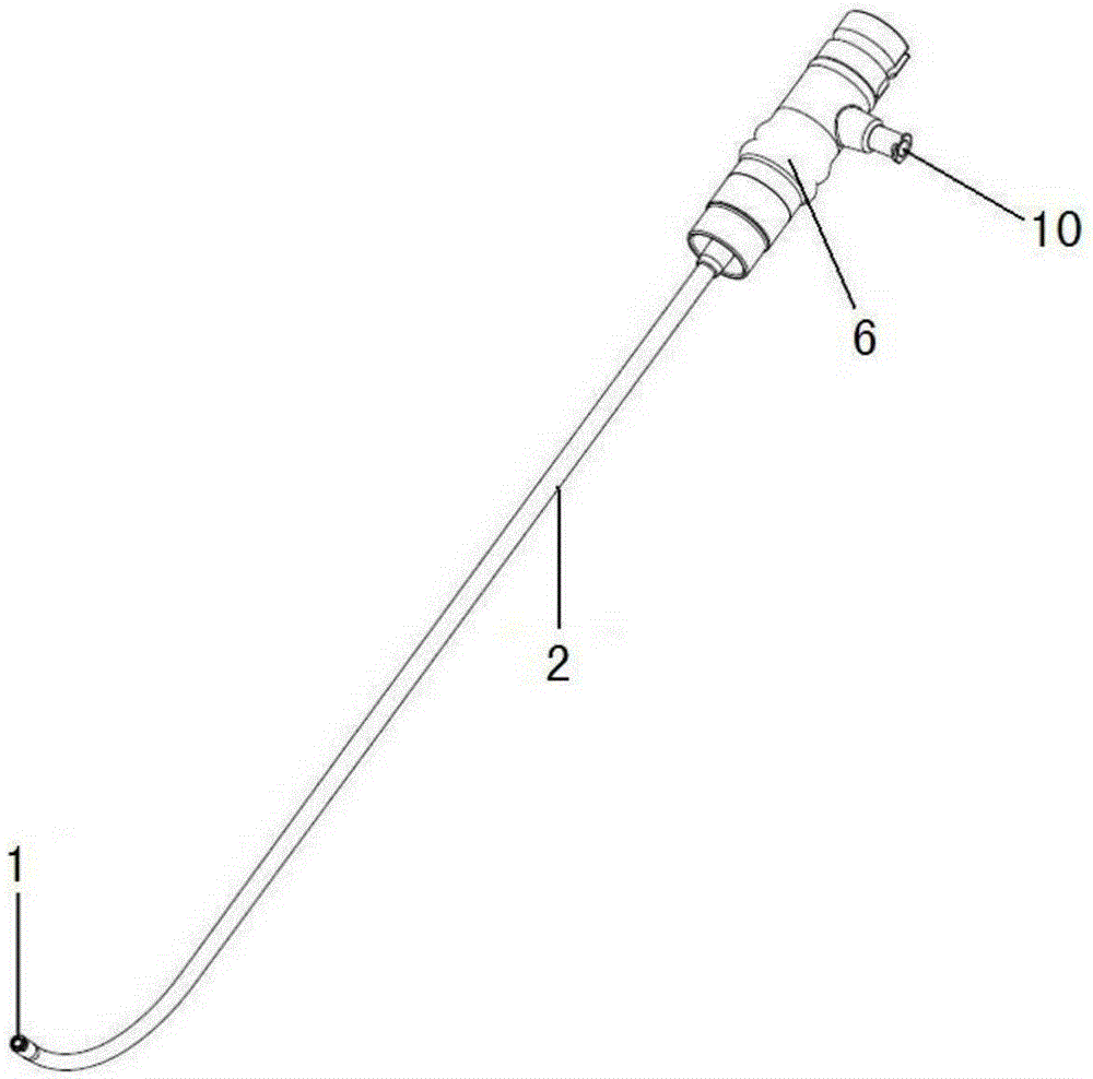
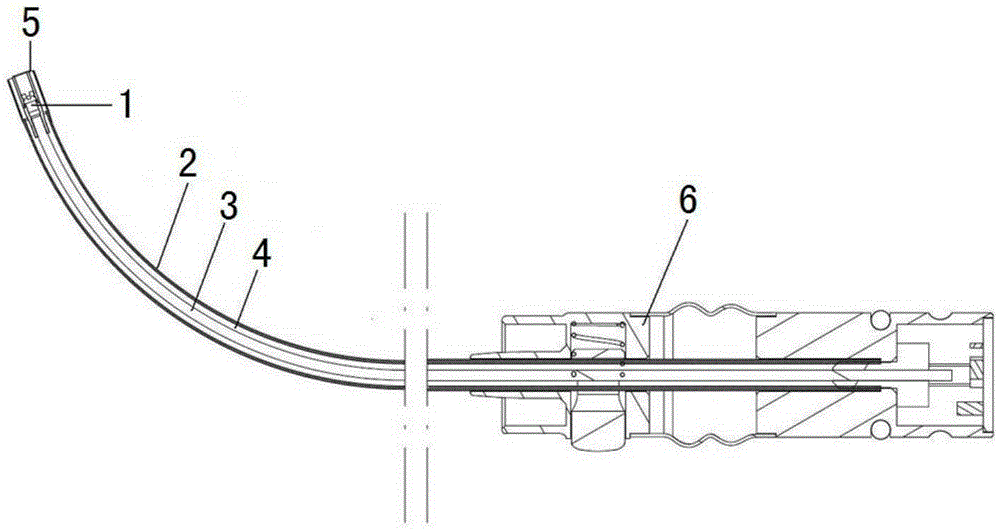
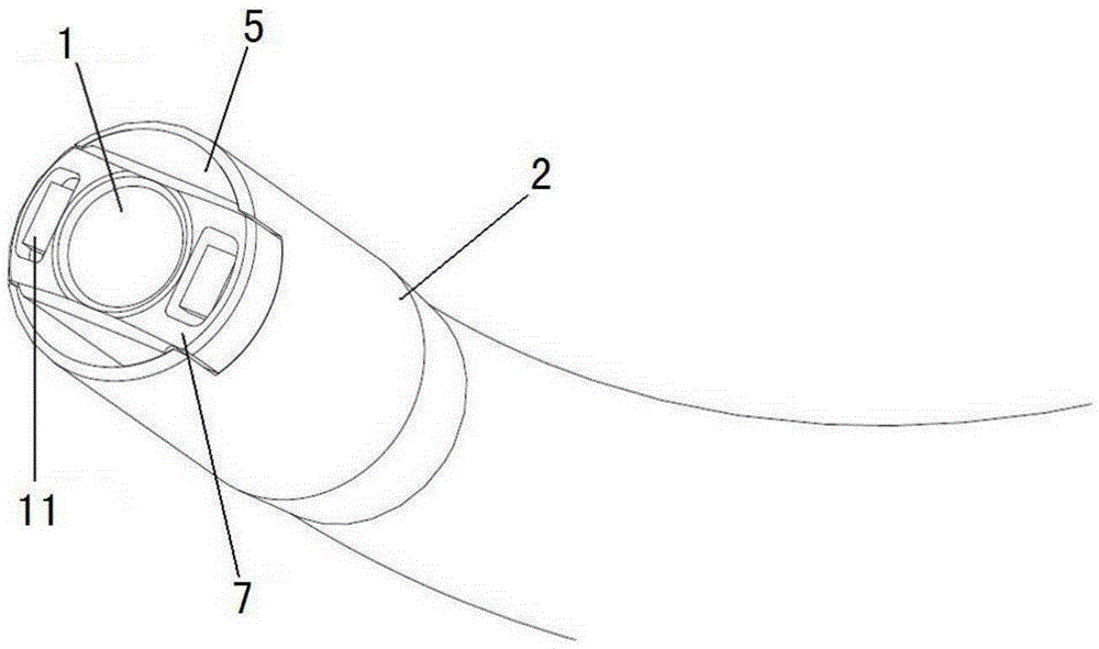
[0065] Figure 1 to Figure 4 Shown is a kind of electronic laryngoscope of the present invention, and the present invention has the basic structure of traditional electronic laryngoscope, promptly its whole comprises: camera module 1 with camera, hollow connecting rod 3, handle 6 and control display module ( Not shown in the figure); wherein, the front end of the connecting rod 3 is connected to the camera module 1, the rear end of the connecting rod 3 is connected to the handle 6, and the rear end of the handle 6 is further connected to the control display module; the rod of the co...


PUM


Abstract

The present invention relates to an electronic laryngoscope. The electronic laryngoscope comprises a camera module with a camera, a hollow connecting rod, a handle and a control display module, wherein the front end of the connecting rod is connected with the camera module, the rear end of the connecting rod is connected with the handle, and the rear end portion of the handle is connected with the control display module; a hollow pipe, the internal pipe diameter of which is greater than the external rod diameter of the connecting rod; a connecting device connecting the hollow pipe and the camera module and / or the connecting rod; and at least one light guide module including a guiding light source and a control device which is connected with the guiding light source and used for controlling the guiding light source. The electronic laryngoscope is simple in structure and convenient to use, the inserting process of the electronic laryngoscope is guided, discovered lesions can be treated when the nasopharynx of a patient is inspected, and damage to the patient is reduced.

Description

technical field [0001] The invention relates to the field of medical instruments, in particular to an electronic laryngoscope. Background technique [0002] The electronic laryngoscope is generally composed of a camera, a hollow hard tube (or "connecting rod"), a handle and a control display module; the front end of the hollow hard tube is equipped with a camera, and the rear end is fixedly connected to the handle, and wires can be passed inside it. ; The rear of the handle is connected with a control display module. In the diagnosis and treatment process using the electronic laryngoscope, the electronic laryngoscope is generally used with a tracheal hose (or "tracheal intubation", or "tracheal tube", or "insertion tube"), that is, the hollow hard tube of the electronic laryngoscope Inserted into the endotracheal hose, the endotracheal hose is surrounded by a hollow hard tube with a camera and goes deep into the patient's throat. [0003] During use, due to the dark enviro...

Claims


Application Information

Patent Timeline
IPC IPC(8): A61B1/267A61B1/06A61B1/015
Inventor 不公告发明人
Owner SHANGHAI ANQING MEDICAL INSTR
Why Eureka
Eureka Blog
Learn More