Magnetic field generation device

a generation device and magnetic field technology, applied in the direction of measurement devices, magnetic measurements, instruments, etc., can solve the problems of increasing the overall size of the apparatus, and achieve the effect of reducing the uniformity of the magnetic field generated by the main coil, and reducing the magnetic field

Active Publication Date: 2016-05-12
JAPAN SUPERCONDUCTOR TECH
View PDF8 Cites 1 Cited by
  • Summary
  • Abstract
  • Description
  • Claims
  • Application Information

AI Technical Summary

Benefits of technology

[0010]According to the present invention, the variable-current correction coil which generates a magnetic field for correcting the uniformity of a magnetic field generated by the main coil is disposed inside the main coil. Where correction coils or shim coils are disposed outside the main coil, since they generate a magnetic field that is perpendicular to the tape surface of the ReBCO-based superconductive wire rod of the main coil, a shielding current flows through the superconductive layer of the ReBCO-based superconductive wire rod and this shielding current decreases a magnetic field generated by the correction coils or shim coils. As a result, the magnetic field uniformity is lowered. In contrast, a magnetic field generated by the variable-current correction coil which is disposed inside the main coil receives almost no influence from the shielding current flowing through the superconductive layer of the ReBCO-based superconductive wire rod. Therefore, the uniformity of the magnetic field generated by the main coil can be corrected efficiently by the magnetic field generated by the variable-current correction coil and hence the magnetic field uniformity can be increased. Furthermore, disposing the variable-current correction coil inside the main coil can suppress increase of the overall size of the apparatus more than in the case that correction coils or shim coils are disposed outside the main coil.

Problems solved by technology

However, to compensate for magnetic field weakening, it is necessary to increase the correction coils in size, which causes a problem that the overall size of the apparatus is increased.
Disposing separate shim coils also causes a problem that the overall size of the apparatus is increased.

Method used


Image

  • Magnetic field generation device
  • Magnetic field generation device
  • Magnetic field generation device

Examples


embodiment

(Modifications to Embodiment)

[0078]The embodiments of the present invention have been described above. However, they are just specific examples and they do not limit the present invention in particular. Their specific structures etc. can be modified in design as appropriate. The workings and advantages described in the embodiments of the invention are the exemplification of most preferable workings and advantages derived from the present invention, and the workings and advantages of the present invention are not limited to the ones described in the embodiments of the present invention.

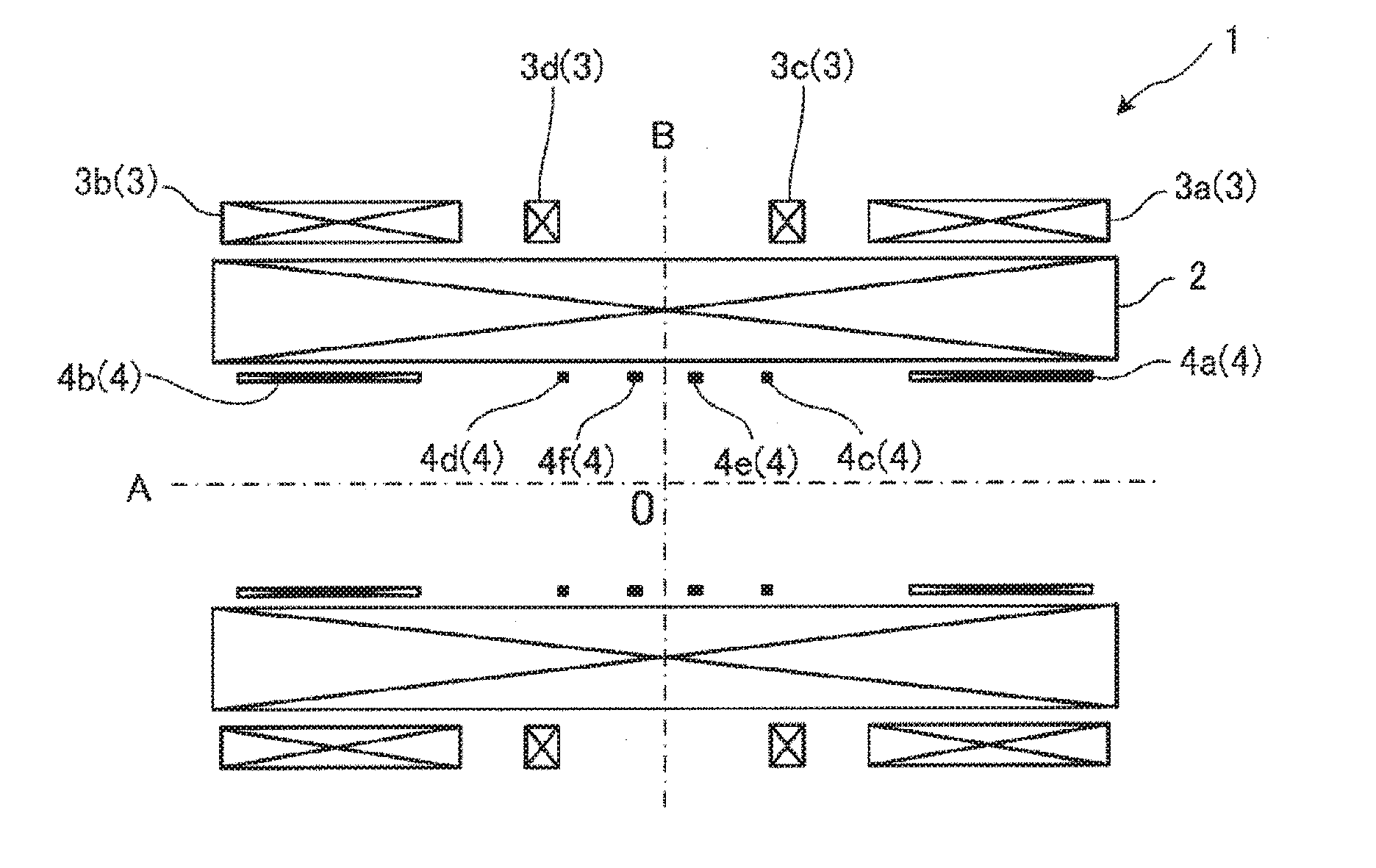
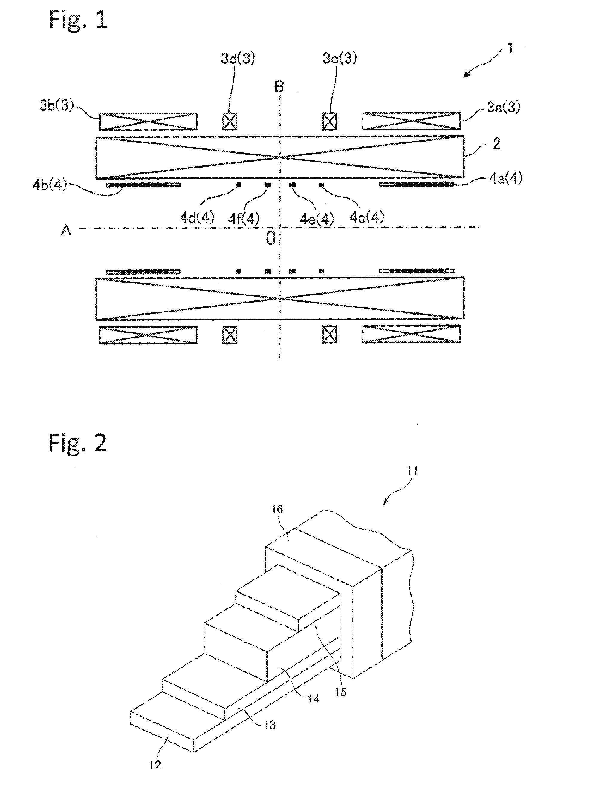
[0079]For example, whereas the magnetic field generation apparatus 1 according to the embodiment is equipped with the correction coils 3, the correction coils 3 may be omitted. In this case, each of the magnetic field components from the B2 component down is adjusted by the variable-current correction coils 4.

[0080]The variable-current correction coils 4 may be one formed by winding a ReBCO-based super...


PUM


Abstract

A magnetic field generation apparatus includes a main coil and a variable-current correction coil. The main coil is formed by winding a ReBCO-based superconductive wire rod and generates a magnetic field in a measurement space. The variable-current correction coil is variable in a value of a current, coaxial with the main coil and disposed inside the main coil, and generates a magnetic field which corrects a uniformity of the magnetic field generated by the main coil.

Description

TECHNICAL FIELD[0001]The present invention relates to a magnetic field generation apparatus applied in an NMR (Nuclear Magnetic Resonance) instrument or an MRI instrument.BACKGROUND ART[0002]Conventionally, Nb3Sn superconductive wire rods disclosed in Patent Document 1, NbTi superconductive wire rods, Nb3Al superconductive wire rods, etc. are used as windings of superconducting coils used in NMR instruments and MRI instruments.PRIOR ART DOCUMENTSPatent Documents[0003]Patent Document 1: JP-B-3-55011SUMMARY OF ME INVENTIONProblems to Be Solved by the Invention[0004]ReBCO-based superconductive wire rods as typified by Y-based ones and Gd-based ones are expected to expand in uses because they have better properties than metallic superconductive wire rods that are currently in industrial use and they enable a flow of superconductive current at temperatures higher than the liquid helium temperature and hence can obtain a strong magnetic field even if not cooled to the liquid helium temper...

Claims


Application Information

Patent Timeline
Patent Type & Authority Applications(United States)
IPC IPC(8): G01R33/3815G01R33/3875
CPCG01R33/3875G01R33/3815
Inventor HAMADA, MAMORUMAEDA, HIDEAKIYANAGISAWA, YOSHINORINAKAGOME, HIDEKI
Owner JAPAN SUPERCONDUCTOR TECH
Why Eureka
Try Eureka