Apparatus and method for in situ current measurement in a conductor

A technology of conductors and conductive structures, which is applied in the direction of measuring devices, measuring magnetic variables, measuring electrical variables, etc., and can solve problems such as occupying a large space, limiting high-precision current sensing, and being expensive

Inactive Publication Date: 2015-10-14
TEXAS INSTR INC
View PDF6 Cites 8 Cited by
  • Summary
  • Abstract
  • Description
  • Claims
  • Application Information

AI Technical Summary

Problems solved by technology

However, this multiple sensor technology is more expensive than a single sensor solution and takes up a lot of space on the area around the conductor of interest
In addition, magnetic field s...

Method used


Image

  • Apparatus and method for in situ current measurement in a conductor
  • Apparatus and method for in situ current measurement in a conductor
  • Apparatus and method for in situ current measurement in a conductor

Examples


Embodiment Construction

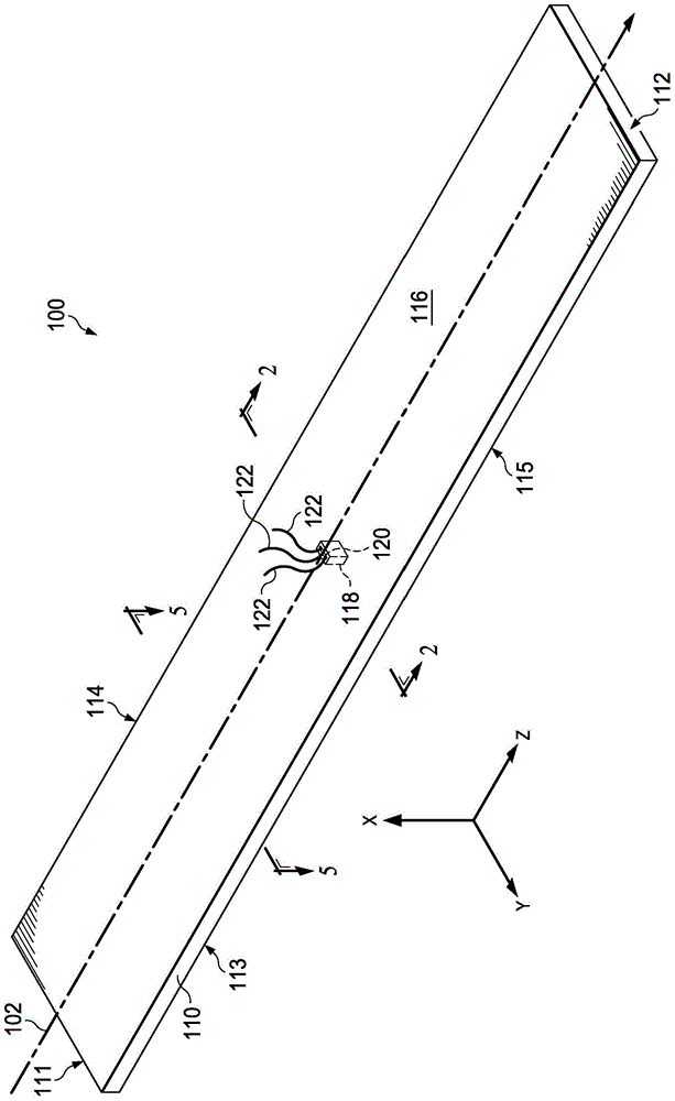
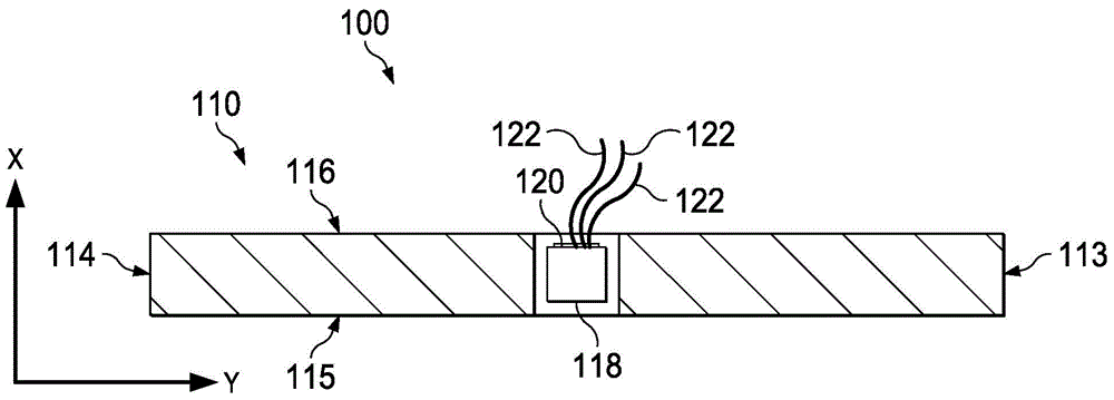
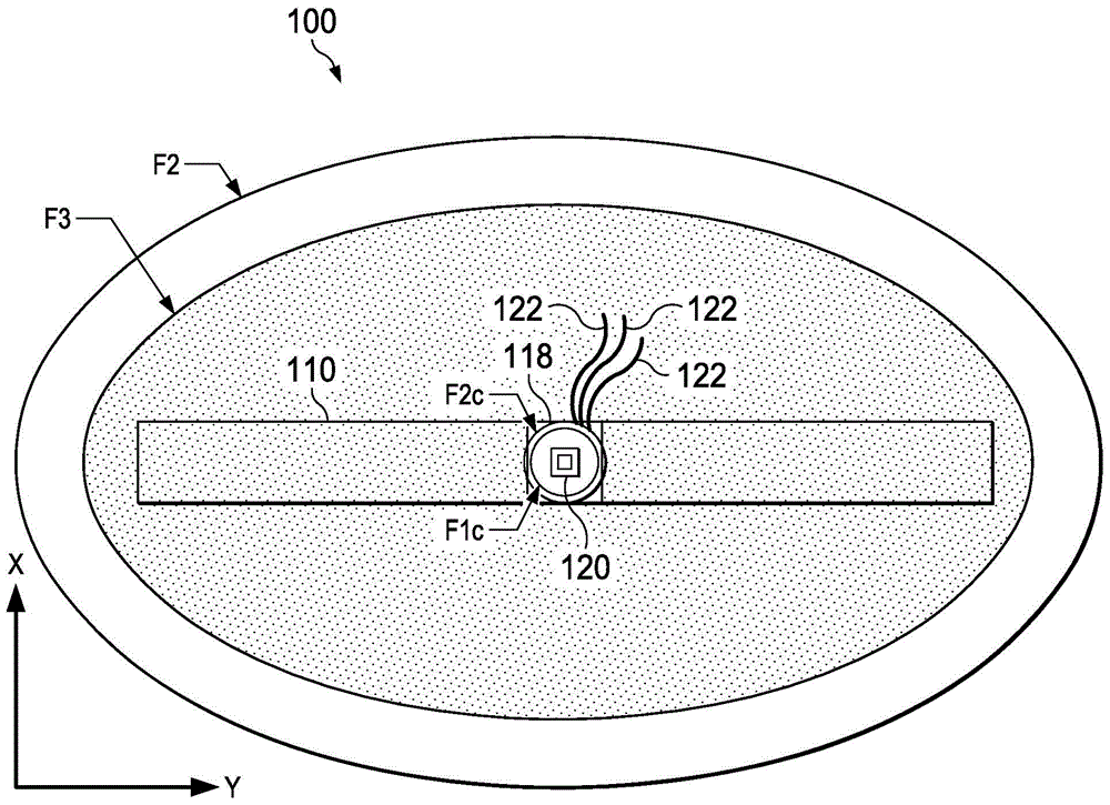
[0031] figure 1A conductor arrangement 100 is shown having an electrically conductive busbar structure 110 for conducting current in a longitudinal direction 102 . For reference only, the figures include examples of arrows representing X, Y, and Z coordinate axes. The illustrated longitudinal extent of the bus bar 110 is generally straight (eg, along the Z axis), although curved, serpentine, curvilinear or other longitudinal conductor structures 110 could be used. In the illustrated example, the busbar 110 includes first and second longitudinal ends 111 and 112, respectively, and has a generally rectangular shape with a periphery between the ends 111 and 112, the rectangular shape defined by a top surface or a second One side 116 , a bottom or second side 115 , and side opposing faces 113 and 114 are defined. The bus bar 110 includes a slot 118 extending inwardly of the top surface 116 in which a magnetometer or current sensor device 120 is positioned. In the illustrated ex...


PUM


Abstract

Improved current sensing methods and apparatus and conductor apparatus are presented for sensing current in a bus bar or other conductor using one or more circular magnetic sensors or multiple magnetic sensors disposed on a substrate in a pattern surrounding a longitudinal path within the outer periphery of the conductor to avoid or mitigate sensed magnetic field crosstalk and to facilitate use of high sensitivity magnetic sensors at locations inside the conductor periphery in which the magnetic field is relatively small.

Description

technical field [0001] The present invention relates to a current measuring device and, more particularly, to a method and apparatus for measuring current using a sensor arrangement within a conductor. Background technique [0002] Current measurement is used in a variety of applications such as closed-loop feedback control of power distribution systems where the controller operates based on the measured current flowing in a specific circuit. For example, a switching power supply can be operated to regulate the output current, and a feedback loop can be formed to provide the power supply controller with an estimate of the output current flowing to the load. Current flowing through a conductor can be sensed by measuring the voltage across a sense resistor connected in series with the conductor, but this method requires the dissipation of energy through the sense resistor. To overcome this difficulty, magnetic sensor technology has been developed in which one or more sensors ...

Claims


Application Information

Patent Timeline
IPC IPC(8): G01R19/00
CPCG01R33/02G01R15/148G01R15/207G01R33/09G01R33/0005G01R15/20
Inventor M·V·伊万诺夫S·R·P·辰奴帕缇V·谢弗
Owner TEXAS INSTR INC
Why Eureka
Try Eureka