Magnetic field generator and its manufacturing method

a generator and magnetic field technology, applied in the direction of magnets, magnets, instruments, etc., can solve the problems of large demagnetization, use of increased magnets and decreased efficiency, and full advantage of magnetic characteristics, and achieve the effect of low magnetization rate, stable magnetic field and low cos

Inactive Publication Date: 2005-05-05
HITACHI METALS LTD
View PDF12 Cites 9 Cited by
  • Summary
  • Abstract
  • Description
  • Claims
  • Application Information

AI Technical Summary

Benefits of technology

[0024] In this invention, a magnet is magnetized to a magnetization rate exceeding 99.9% and then demagnetized to a lower magnetization rate. This assures that a magnetic field generated by a magnetic field generator using this magnet is stable over a long time, making possible to

Problems solved by technology

It should be noted here that if the final magnetization rate of the R—Fe—B magnet is less than 80%, it becomes impossible to take full advantage of magnetic characteristics of the magnet, which leads to use of an incr

Method used


Image

  • Magnetic field generator and its manufacturing method
  • Magnetic field generator and its manufacturing method
  • Magnetic field generator and its manufacturing method

Examples


Embodiment Construction

[0034] Hereinafter, an embodiment of the present invention will be described with reference to the drawings.

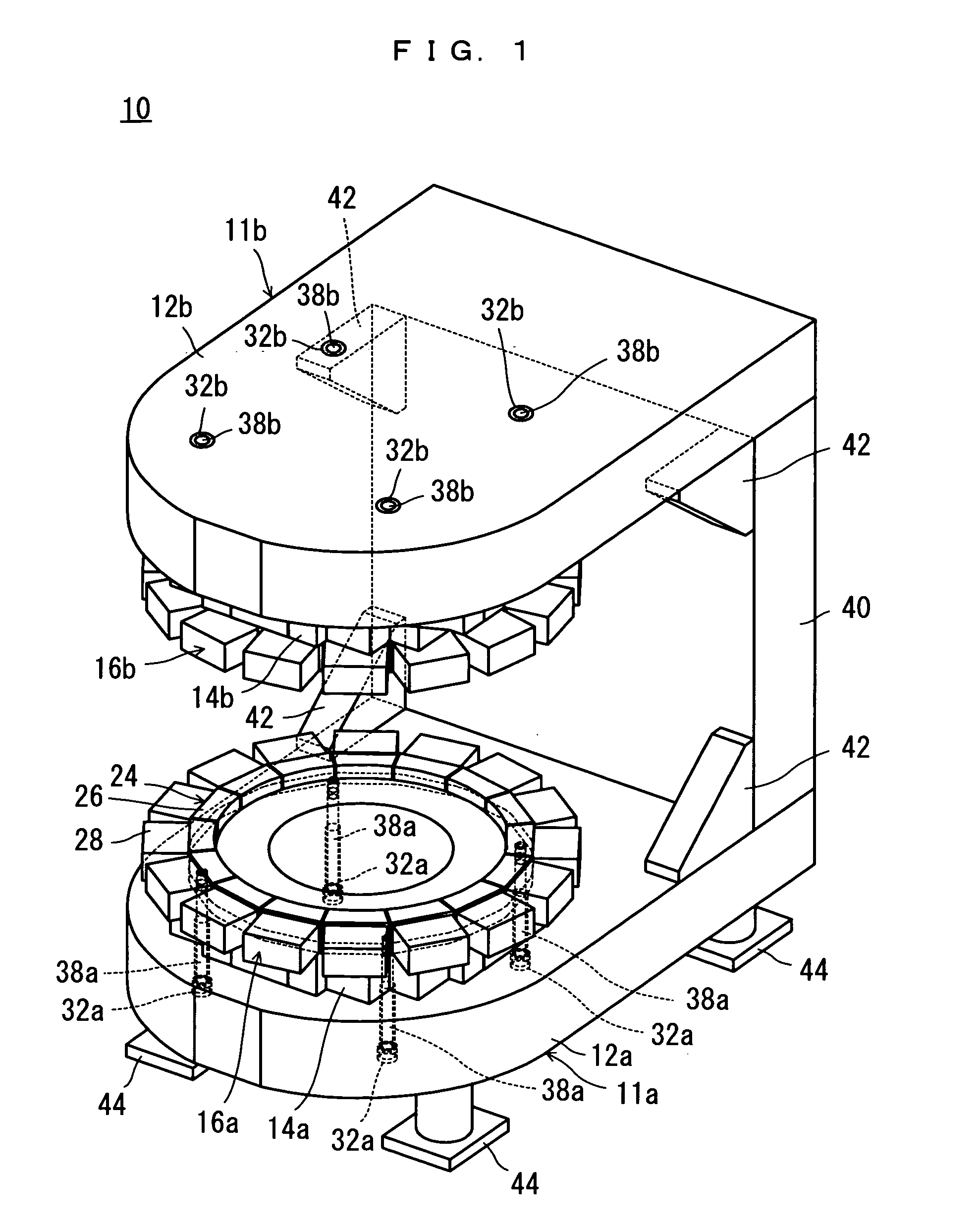
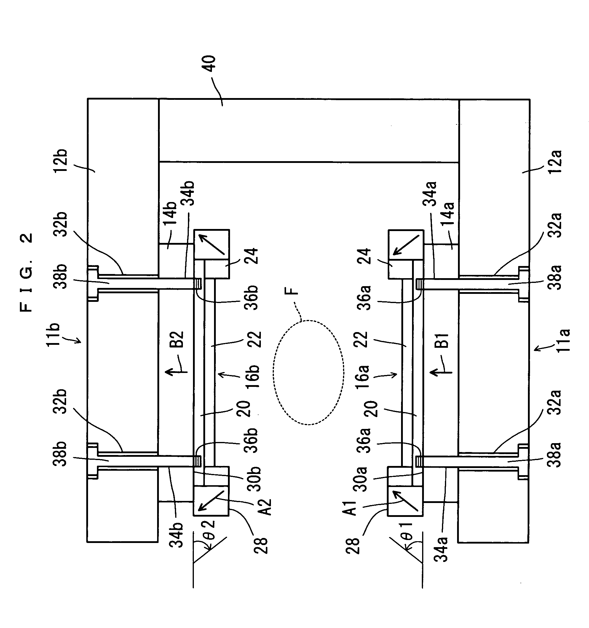
[0035] Referring to FIG. 1 and FIG. 2, a magnetic field generator 10 for MRI as an embodiment of the present invention is an open type magnetic field generator for MRI, and includes a pair of pole-piece units 11a, 11b which are faced to each other forming a space in between.

[0036] The pole-piece units 11a, 11b include plate yokes 12a, 12b respectively. This pair of plate yokes 12a, 12b are opposed to each other, with their opposing faces provided with permanent magnet assemblies 14a, 14b respectively. The permanent magnet assemblies 14a, 14b have faces opposing to each other, to which pole pieces 16a, 16b are fixed respectively.

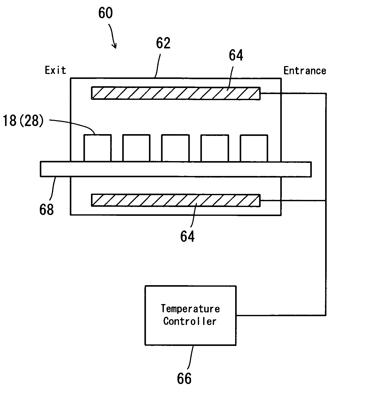
[0037] As is clear from FIG. 3, the permanent magnet assemblies 14a, 14b each include a plurality of parallelepiped permanent magnets 18. The permanent magnets 18 are provided by e.g. NEOMAX-47 (manufactured by Sumitomo Special Metals Co., Ltd ), or ...


PUM

PropertyMeasurementUnit
Temperatureaaaaaaaaaa
Fractionaaaaaaaaaa

Abstract

There is provided a magnetic field generator (10) and a method of manufacturing it, capable of reducing decline in the magnetic field intensity and deterioration of magnetic field uniformity during transportation.
The magnetic field generator (10) includes a pair of plate yokes (12a), (12b). The plate yokes (12a), (12b) are opposed to each other, with their opposing faces provided with permanent magnet assemblies (14a), (14b) respectively. The permanent magnet assemblies (14a), (14b) have faces opposing to each other, to which pole pieces (16a), (16b) are fixed respectively. The permanent magnet assemblies (14a), (14b) include permanent magnets (18). The pole pieces (16a), (16b) include annular projection (24) and permanent magnets (28) for prevention of magnetic flux leakage provided on an outer side surface of the annular projection (24). The permanent magnets (18), (28) include R—Fe—B magnets magnetized to a magnetization rate not smaller than 80% and not greater than 99.9%. When manufactured, the assembled magnetic field generator (10) is heated in its entirety at a temperature not lower than 40° C. and not higher than 70° C.

Description

TECHNICAL FIELD [0001] The present invention relates to a magnetic field generator and a manufacturing method thereof. More specifically, the present invention relates to a magnetic field generator for MRI and a manufacturing method thereof. BACKGROUND ART [0002] Conventionally, a magnetic field generator for MRI receives complete adjustment of magnetic field intensity and magnetic field uniformity before shipment, and then transported to destination in a container for example. [0003] However, despite such deliberate procedures, it sometimes happens that upon arrival, the magnetic field intensity has decreased, or the magnetic field uniformity has deteriorated down below an acceptable limit, and therefore readjustment must be made to the magnetic field generator. [0004] This problem is particularly conspicuous in a magnetic field generator which makes use of magnetic flux leakage prevention magnets in order to reduce magnetic flux leakage and to concentrate magnetic flux from the ma...

Claims


Application Information

Patent Timeline
IPC IPC(8): G01R33/38G01R33/383G01R33/421H01F7/02
CPCG01R33/3806G01R33/383Y10T29/49075H01F7/0278Y10T29/49073G01R33/421
Inventor AOKI, MASAAKITSUZAKI, TSUYOSHI
Owner HITACHI METALS LTD
Why Eureka
Try Eureka