Liquid crystal display device

a liquid crystal display and display device technology, applied in non-linear optics, instruments, optics, etc., can solve the problems of degrading image quality and high cost of louver films, and achieve excellent image quality, narrow viewing angle, and excellent image quality.

Inactive Publication Date: 2016-05-12
NITTO DENKO CORP
View PDF4 Cites 10 Cited by
  • Summary
  • Abstract
  • Description
  • Claims
  • Application Information

AI Technical Summary

Benefits of technology

[0010]According to the embodiments of the present invention, the liquid crystal display device narrow in viewing angle and capable of excellent image quality may be provided by including the prism sheet that is convex on the opposite side (back surface side) from the viewer side and the visible light absorber that is arranged on the back surface side of the light guide plate. More specifically, replacing a reflecting plate that is arranged on the back surface side of a light guide plate in a liquid crystal display device of the related art with the visible light absorber helps the prism sheet that is arranged so as to be convex on the back surface side exert a light condensing effect to a markedly high level, thereby enabling the liquid crystal display device to narrow the viewing angle without using a louver film. With no need for a louver film, the liquid crystal display device of the embodiments of the present invention also has excellent image quality and may be provided inexpensively.

Problems solved by technology

However, using a louver film on a liquid crystal display device causes moiré patterns, streaks, hue fluctuations, and the like, which significantly degrade image quality.
Another problem is that louver films are expensive.

Method used


Image

  • Liquid crystal display device
  • Liquid crystal display device
  • Liquid crystal display device

Examples


example 1

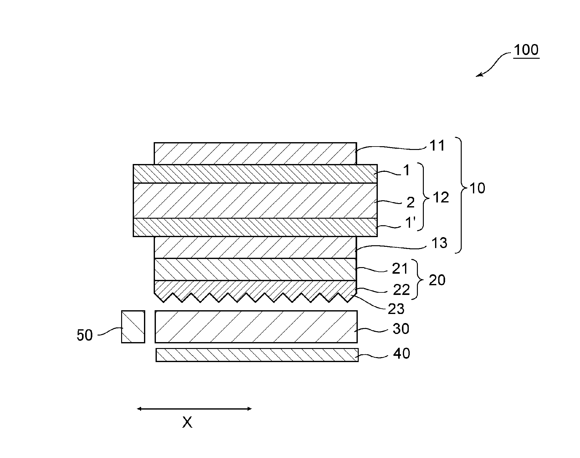
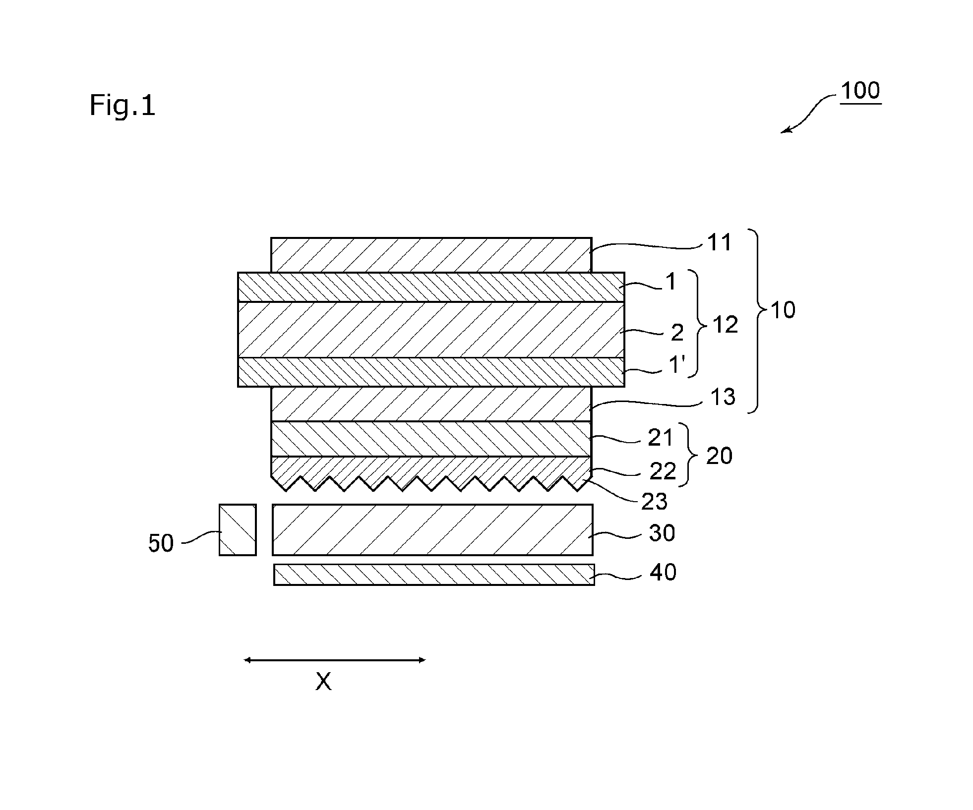
[0067]A liquid crystal display device was prepared that included, from the viewer side in order, a liquid crystal panel (the liquid crystal panel mounted to a VAIO S-series computer manufactured by Sony Corporation, configuration: viewer-side polarizing plate / TN-mode liquid crystal cell / back surface-side polarizing plate), a prism sheet, and a backlight unit.

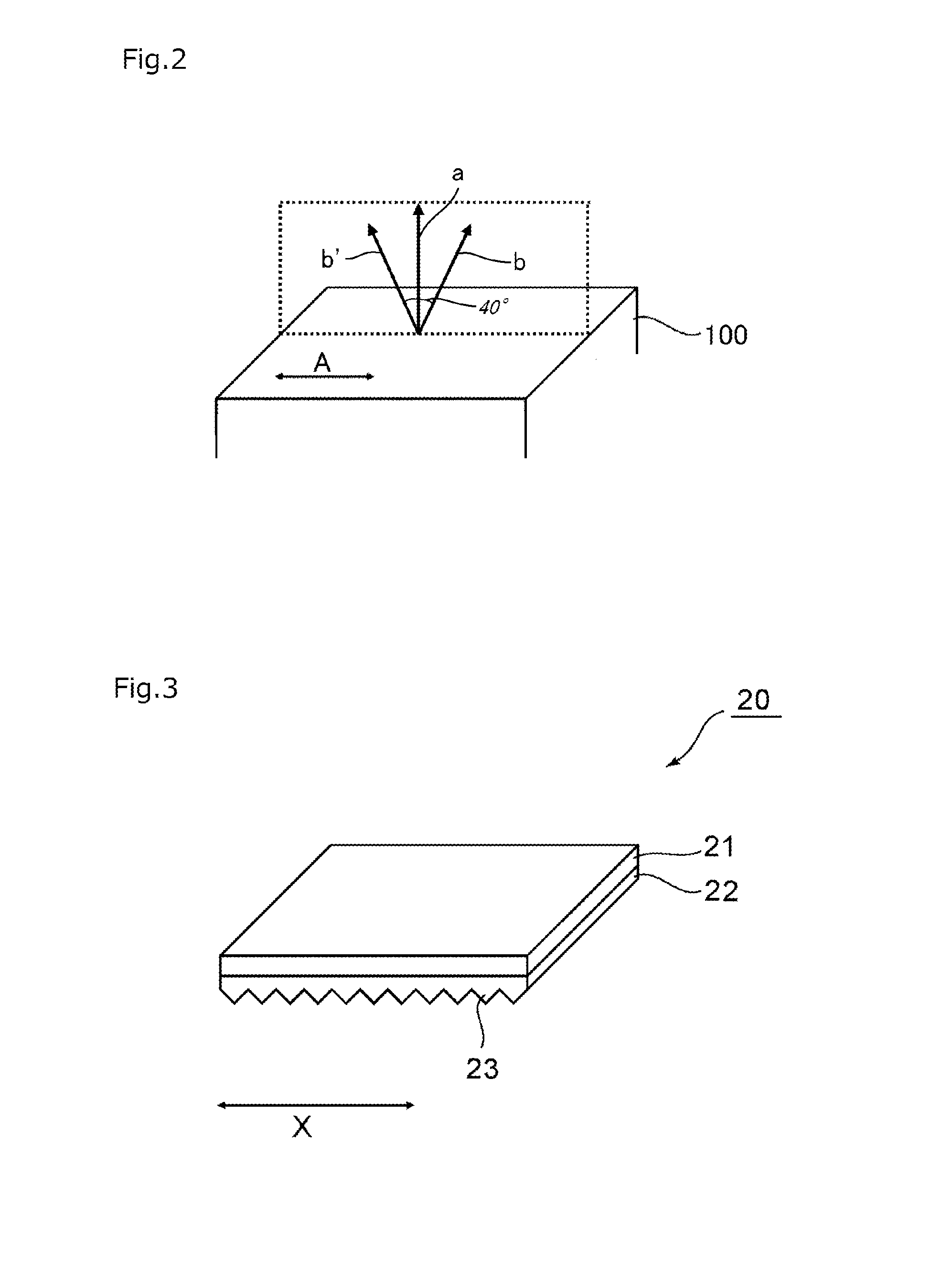
[0068]The prism sheet used includes a base material portion and a prism portion in which a plurality of unit prisms each having a triangular prism shape are aligned. The prism sheet was arranged so that its convex portion faced toward the back surface side.

[0069]The backlight used includes a light guide plate, an LED light source, which is arranged in a place corresponding to a side surface of the light guide plate, and a visible light absorber (construction paper “C-855”, a product of Daio Paper Corporation, luminous reflectance: 70), which is arranged on the back surface side of the light guide plate.

[0070]The luminance of the...

example 2

[0073]A liquid crystal display device was prepared in the same way as in Example 1, except that a reflective polarizing plate was arranged between the liquid crystal panel and the prism sheet. The resultant liquid crystal display device was evaluated by the same method that was used in Example 1. Results thereof are shown in Table 1 and FIG. 4 (b). The image quality of the obtained liquid crystal display device was checked by the evaluation method (3) to reveal that fine image quality without visible graininess, moiré patterns, and blurring was acquired.


PUM

PropertyMeasurementUnit
luminous reflectanceaaaaaaaaaa
polar angleaaaaaaaaaa

Abstract

Provided is a liquid crystal display device that is narrow in viewing angle and that is capable of excellent image quality. The liquid crystal display device of the present invention includes: a liquid crystal panel; a prism sheet; a light guide plate; and a visible light absorber, which are provided in the stated order from a viewer side. The prism sheet has a convex portion on the opposite side from the viewer side. The visible light absorber has a luminous reflectance of 30% or less. In one embodiment, the liquid crystal display device of the present invention is free from a reflective polarizing plate. In one embodiment, the prism sheet includes a plurality of unit prisms, which are each shaped to have a triangular prism shape and which are arranged side by side.

Description

TECHNICAL FIELD[0001]The present invention relates to a liquid crystal display device.BACKGROUND ART[0002]Liquid crystal display devices are usually demanded to have a wide viewing angle when used in scenes where the viewer position is not fixed and the display device is supposed to be viewed from every angle (for example, in electronic advertisement and in television sets and personal computers for normal uses). To accomplish a wide viewing angle, various technologies that use a diffusion sheet, a prism sheet, a wide viewing angle liquid crystal panel, a wide viewing angle polarizing plate, or the like are being investigated. On the other hand, liquid crystal display devices that are capable of displaying an image at a narrow viewing angle (for example, liquid crystal display devices for use in cellular phones, notebook computers used in public places, automated teller machines, and seat monitors on rides) are also in demand for the prevention of screen peeking and other purposes w...

Claims


Application Information

Patent Timeline
Patent Type & Authority Applications(United States)
IPC IPC(8): G02F1/1335
CPCG02F1/133524G02F1/1335G02F1/133606
Inventor MAESAWA, SHOUHEINAKAMURA, KOZOFUCHIDA, TAKEHITOTAKEMOTO, HIROYUKI
Owner NITTO DENKO CORP
Why Eureka
Try Eureka