
Cutting Knife

Active Publication Date: 2016-05-19
KII TEKU INC
View PDF1 Cites 3 Cited by
  • Summary
  • Abstract
  • Description
  • Claims
  • Application Information

AI Technical Summary

Benefits of technology

The present invention relates to cutting knives with a smooth and efficient movement within a guide track. The cutting knife has a smooth main body with a non-sticking coating and a protrusion that prevents adhesion to the guide track. Additionally, the invention includes a movement limiting member that ensures the cutting knife moves within the guide track and a protrusion that cooperates with the guide track to ensure smooth movement. These features make the cutting knife easier to use and more efficient in cutting.

Problems solved by technology

Firstly, and only occasionally, individual cutter knives employed in the apparatus as described in the previous patent, when rotated at predetermined operational speeds, occasionally would prematurely move or be ejected to a radially outwardly extended cutting position and then engage the elongated food product being processed without being intentionally deployed or actuated by the cutting apparatus.
This premature deployment, or movement of a cutting knife to the radially extended cutting position could occasionally cause the knife to become damaged.
In addition to the foregoing, the cutting knives employed, to date, have been fabricated from various materials and due to normal wear and tear, and routine operating conditions, such prior art cutting knives have occasionally broken, and have needed to be replaced.
This type of wear related failure is typically expected, from time-to-time, in devices of this type.
However, depending upon the product to be inspected and cut, the replacement of these damaged cutting knives can sometimes be time consuming, and inconvenient during typical food processing operations.
Still further, another problem attendant with the prior art devices, as utilized heretofore, is that, on occasion, such cutting knives have not deployed at all in view of an adverse amount friction or other conditions existing within an associated knife guidance track which defines the path of travel for the individual cutting knives.
While various solutions have been suggested to address the foregoing problems, the premature deployment or the failure to deploy a cutting knife during routine food processing operations has been perceived to be a problem which has not found an acceptable solution.

Method used


Image

  • Cutting Knife
  • Cutting Knife
  • Cutting Knife

Examples


Embodiment Construction

[0019]This disclosure of the invention is submitted in furtherance of the constitutional purposes of the U.S. Patent Laws “to promote the progress of science and useful arts” (Article I, Section 8).

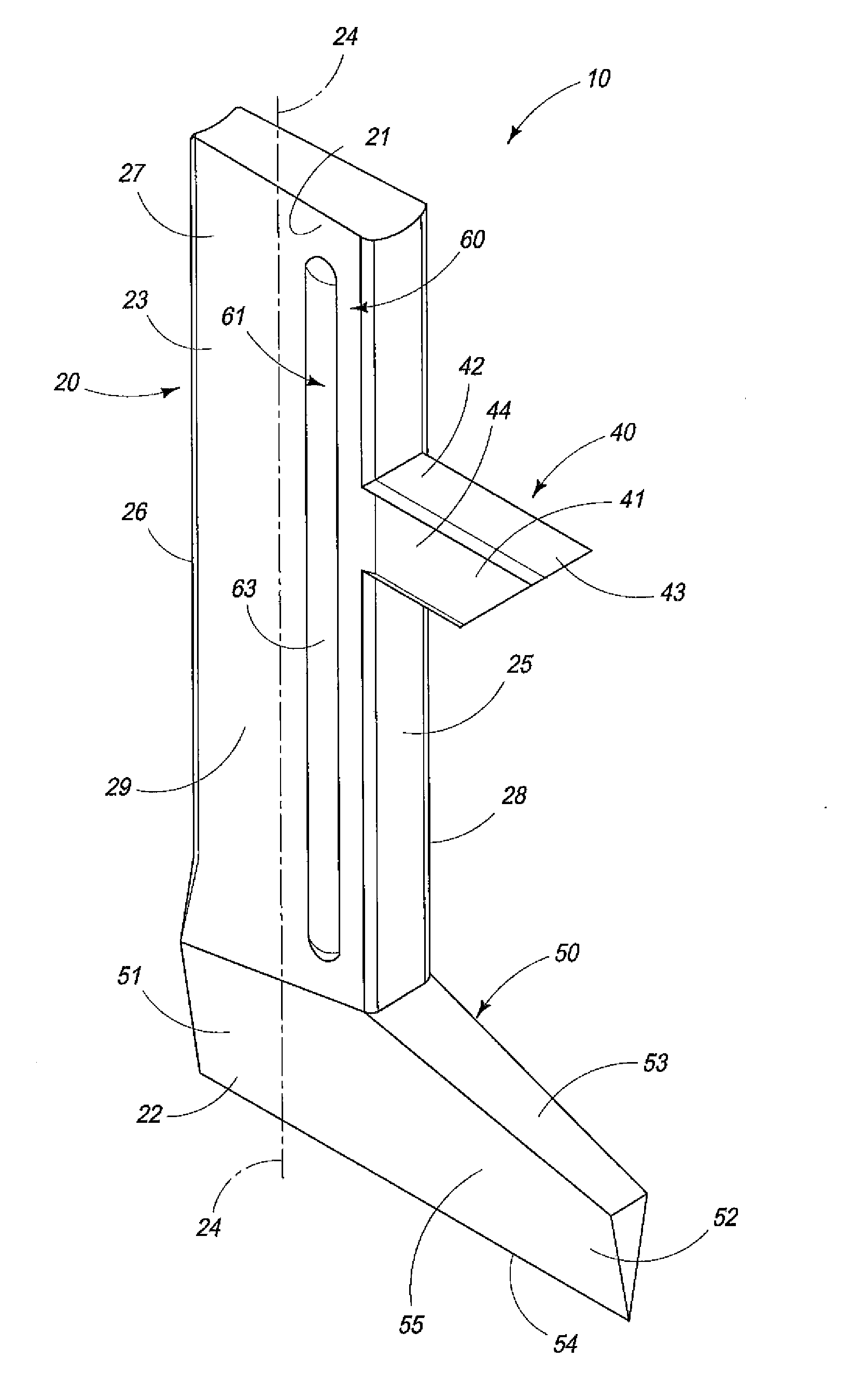
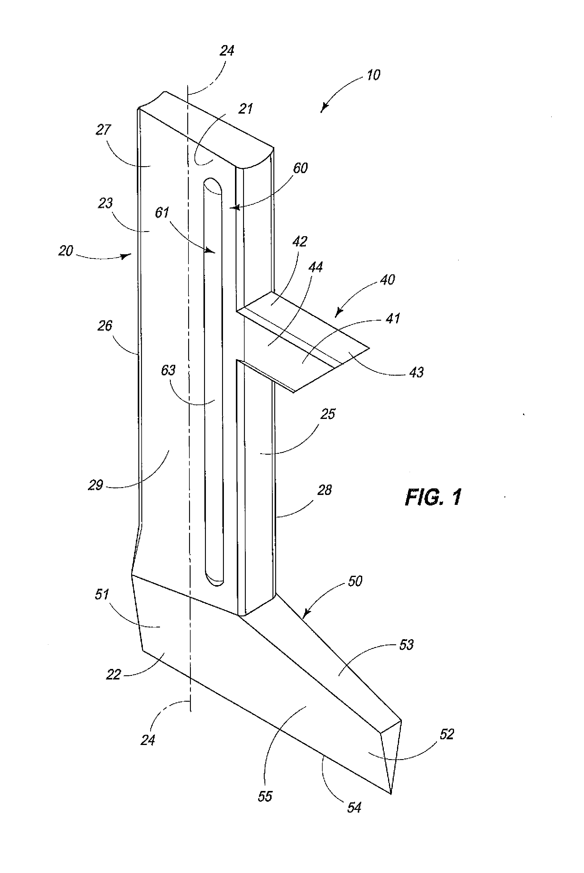
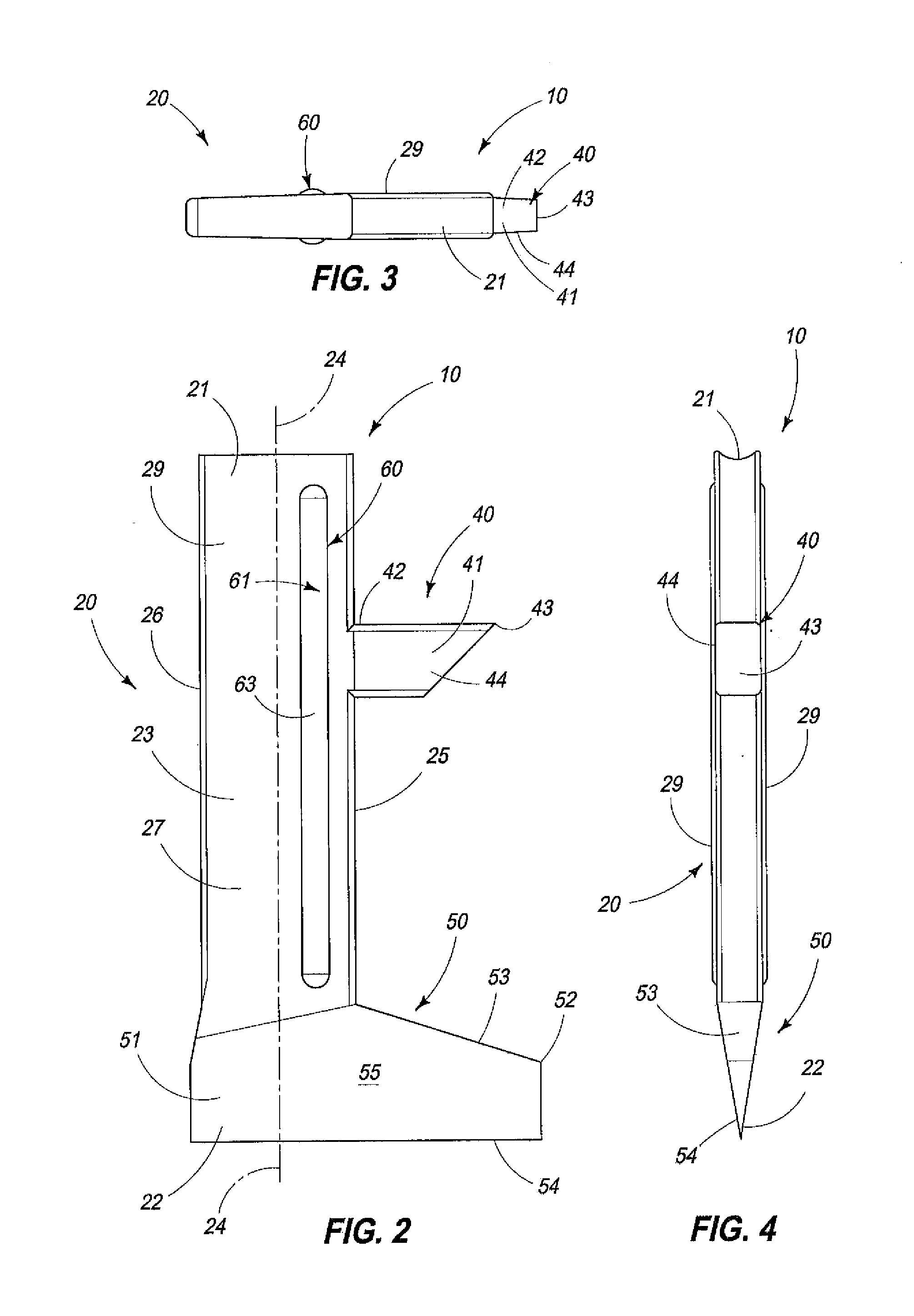
[0020]Referring now to FIG. 9, it will be seen that the cutting knife of the present invention, and which is generally indicated by the numeral 10 is utilized, in combination with, a rotatable knife support ring which is generally indicated by the numeral 11. The rotatable knife support ring 11 defines a multiplicity of radially extending, individual, knife guidance tracks 12. The individual knife guidance tracks 12 are each defined by a pair of spaced, substantially parallel sidewalls which are indicated by the numeral 13. The spaced sidewalls define, at least in part, a reciprocal path of travel 14 for the individual cutting knives 10, as seen in FIG. 9. The respective cutting knives 10 are moveable from a first, non-cutting position 15, to a second, extended, cutting position 16. In th...


PUM

PropertyMeasurementUnit
Lengthaaaaaaaaaa
Thicknessaaaaaaaaaa
Adhesion strengthaaaaaaaaaa

Abstract

A reciprocally moveable cutting knife is described and which includes an elongated main body having a first, and an opposite, second end for engaging an object of interest; and a protrusion is made integral with the elongated main body and which extends outwardly from a plane which is defined by the outside facing surface of the main body, and which inhibits an adhesion from being created between the outside facing surface of the elongated main body, and the respective sidewalls of a knife guidance track when a source of water wets the outside surface of the elongated main body and the spaced sidewalls of the knife guidance channel.

Description

TECHNICAL FIELD[0001]The present invention relates to a cutting knife which is employed with equipment for detecting defects in elongated articles or other objects of interest, and for cutting or otherwise removing the defects from the articles or objects of interest as the articles are being processed in a high output production facility.BACKGROUND OF THE INVENTION[0002]The present invention as disclosed in the paragraphs which follow is utilized in an inspection and cutting apparatus such as what is shown in U.S. Pat. No. 4,520,702. The contents and teachings of this previous patent is incorporated by reference herein. U.S. Pat. No. 4,520,702 addressed a perceived problem then existing in the industry relative to the processing of elongated articles such as sliced potatoes which are utilized for frozen french fries, and wherein the elongated articles were first aligned in moveable, transversely spaced lanes, and then passed beneath individual lane oriented electro-optical cameras ...

Claims


Application Information

Patent Timeline
IPC IPC(8): B26D1/00B26D1/06
CPCB26D1/06B26D1/0006B26D1/42B26D2001/006B26D1/62B26D1/10B26D7/088Y10T83/4705Y10T83/4812
Inventor CALVERT, SEAN G.JONES, ROBERT E.LOVGREN, BRIAN D.JAUSORO, LOUIS D.
Owner KII TEKU INC
Learn More