
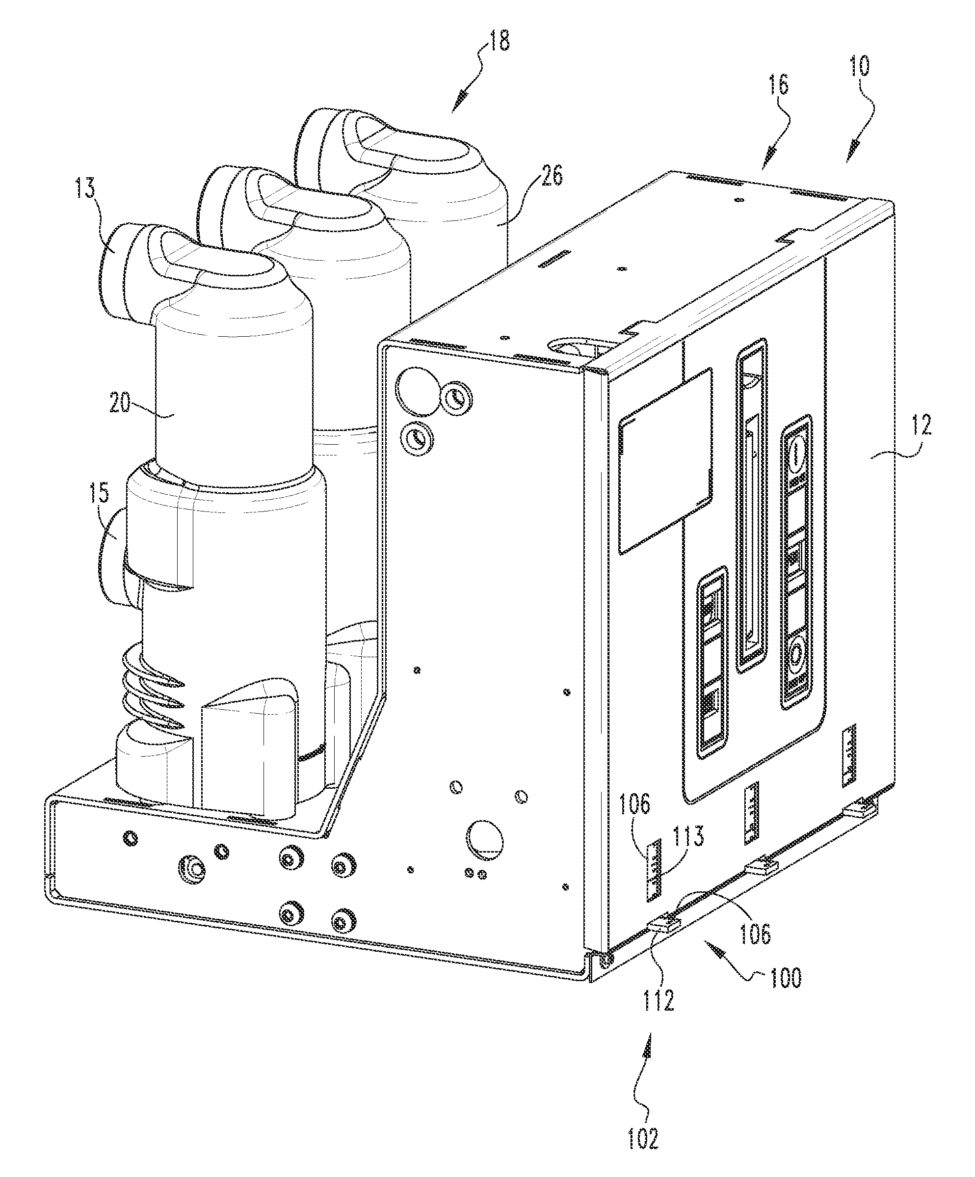
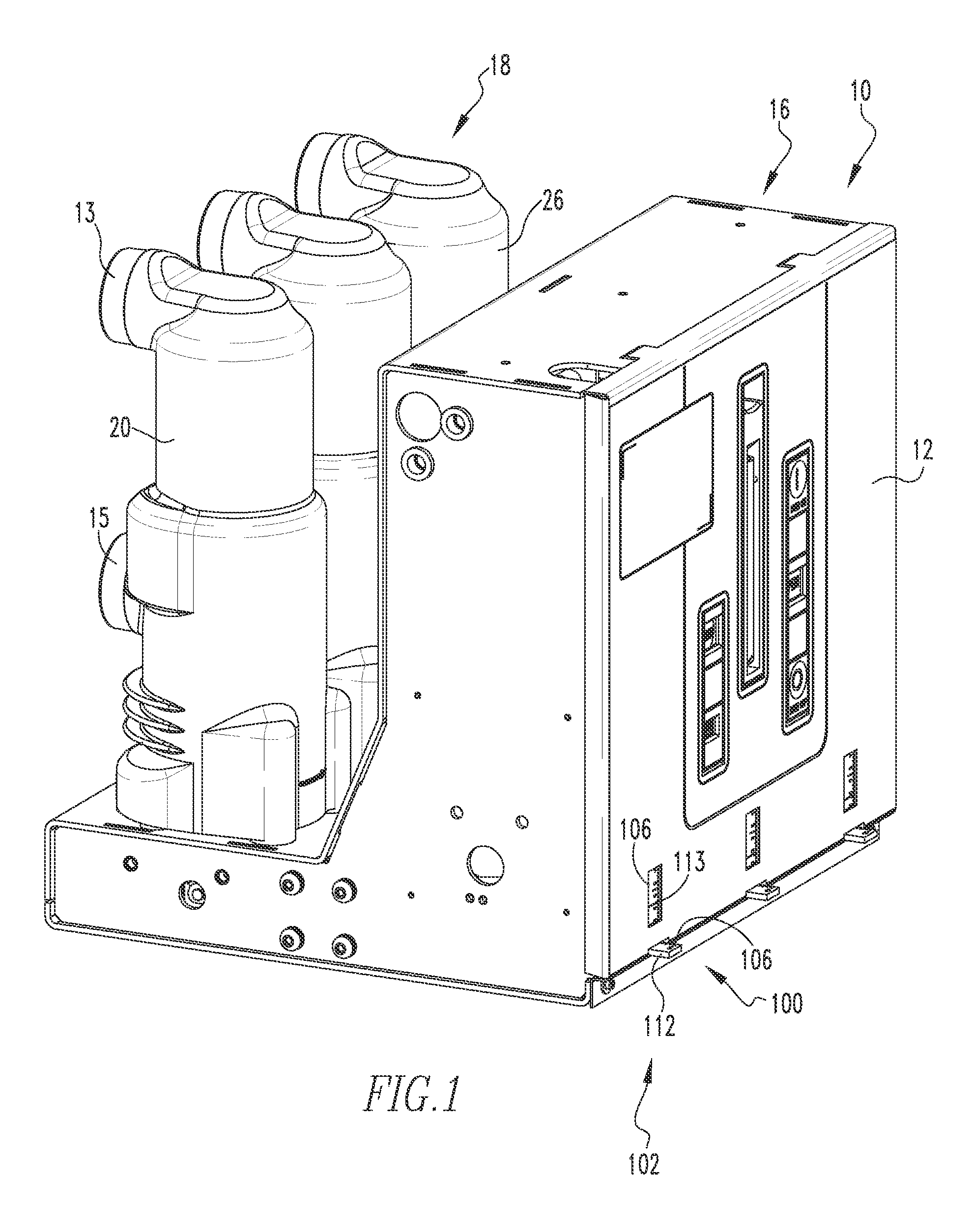
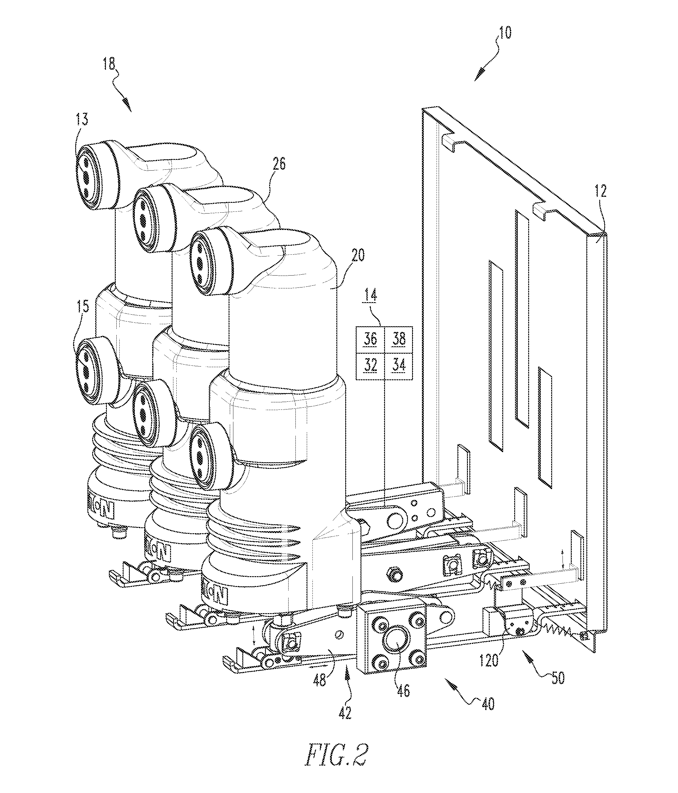
Visible Disconnect Switch Interlock Assembly

a technology of interlocking assembly and disconnect switch, which is applied in the direction of air-break switch, protective switch operation/release mechanism, protective switch details, etc., can solve the problems of not being able to move the circuit breaker assembly contacts, the thickness of the contact assembly is reduced, and the contact may wear

Inactive Publication Date: 2016-05-19
EATON INTELLIGENT POWER LIMITED
View PDF5 Cites 13 Cited by
  • Summary
  • Abstract
  • Description
  • Claims
  • Application Information

AI Technical Summary

Benefits of technology

This patent describes a VDS interlock assembly that allows for the safe and reliable operation of electrical equipment. The assembly includes an interface assembly, an interlock assembly, a mechanical control system interlock interface assembly, and an interlock drive assembly. This interlock assembly is designed to prevent accidental or unauthorized access to electrical equipment, ensuring safety and reliability. Additionally, the patent also includes a modular mounting assembly that allows for easy installation and replacement of the interlock assembly. Overall, this invention provides a reliable and efficient solution for safely and securely controlling the operation of electrical equipment.

Problems solved by technology

Over time the contacts are subject to wear and tear which diminishes the thickness of the contact assemblies.
Further, such constructs provide for a determination of contact wear only when used and do not provide continuous check on the contact characteristics.
The contacts may wear between checks performed during the scheduled maintenance or downtime.
Further, it is not desirable to move the circuit breaker assembly contacts between their first and second positions when the visible disconnect switch contacts are in their open, first positions.
Further, the coupling assemblies for known visible disconnect switches are cumbersome and limit the location of the visible disconnect switch.

Method used


Image

  • Visible Disconnect Switch Interlock Assembly
  • Visible Disconnect Switch Interlock Assembly
  • Visible Disconnect Switch Interlock Assembly

Examples


Embodiment Construction

[0041]It will be appreciated that the specific elements illustrated in the figures herein and described in the following specification are simply exemplary embodiments of the disclosed concept, which are provided as non-limiting examples solely for the purpose of illustration. Therefore, specific dimensions, orientations, assembly, number of components used, embodiment configurations and other physical characteristics related to the embodiments disclosed herein are not to be considered limiting on the scope of the disclosed concept.

[0042]Directional phrases used herein, such as, for example, clockwise, counterclockwise, left, right, top, bottom, upwards, downwards and derivatives thereof, relate to the orientation of the elements shown in the drawings and are not limiting upon the claims unless expressly recited therein.

[0043]As used herein, the singular form of “a,”“an,” and “the” include plural references unless the context clearly dictates otherwise.

[0044]As used herein, the stat...


PUM


Abstract

A visible disconnect switch (VDS) interlock assembly is provided. The VDS interlock assembly is movable between a CBA, first lockout position, wherein a CBA second contact assembly cannot move when a VDS second contact assembly is in a first position, and a VDS, second lockout position, wherein a VDS second contact assembly cannot move when the CBA second contact assembly is in a second position. Further, the VDS interlock assembly is placed in an open position in between where the CBA, first lockout position and the VDS, second lockout position; from the open position the VDS interlock assembly may be moved into one of the CBA, first lockout position or the VDS, second lockout position.

Description

BACKGROUND OF THE INVENTION[0001]1. Field of the Invention[0002]The disclosed and claimed concept relates to a circuit breaker with a visible disconnect switch and, more specifically, to a visible disconnect switch interlock assembly.[0003]2. Background Information[0004]Circuit breaker assemblies (CBA) provide protection for electrical systems from electrical fault conditions such as current overloads, short circuits, and low level voltage conditions. Typically, circuit breakers include a trip device and an operating mechanism. The trip device detects an over-current condition and actuate the operating mechanism. The operating mechanism open and closes, either manually or in response to the trip device, a number of electrical contacts. In particular, vacuum circuit interrupters include separable main contacts disposed within an insulated and / or hermetically sealed housing. Generally, one of the contacts is fixed relative to both the housing and to an external electrical conductor. T...

Claims


Application Information

Patent Timeline
Patent Type & Authority Applications(United States)
IPC IPC(8): H01H71/10H01H9/24
CPCH01H71/10H01H2221/052H01H2205/002H01H9/24H01H31/10H01H31/28H01H33/6661H01H19/14H01H71/1009H01H2235/01
Inventor ASHTEKAR, KOUSTUBH DNYANDEOBENKE, JAMES JEFFERYJENKINS, ZACHARY R.
Owner EATON INTELLIGENT POWER LIMITED
Learn More