
Illuminating helmet cover

a technology of illumination helmets and helmet covers, which is applied in the direction of lighting support devices, lighting and heating apparatus, instruments, etc., can solve the problems of motorized bicycles or riders in a much greater risk of injury or death, bicycles or other motorized cycles are not suitable for use, and both manual cycling and motorized cycling inherently include significant safety risks for those individuals

Inactive Publication Date: 2016-06-02
DAS AYSHETA
View PDF16 Cites 12 Cited by
  • Summary
  • Abstract
  • Description
  • Claims
  • Application Information

AI Technical Summary

Benefits of technology

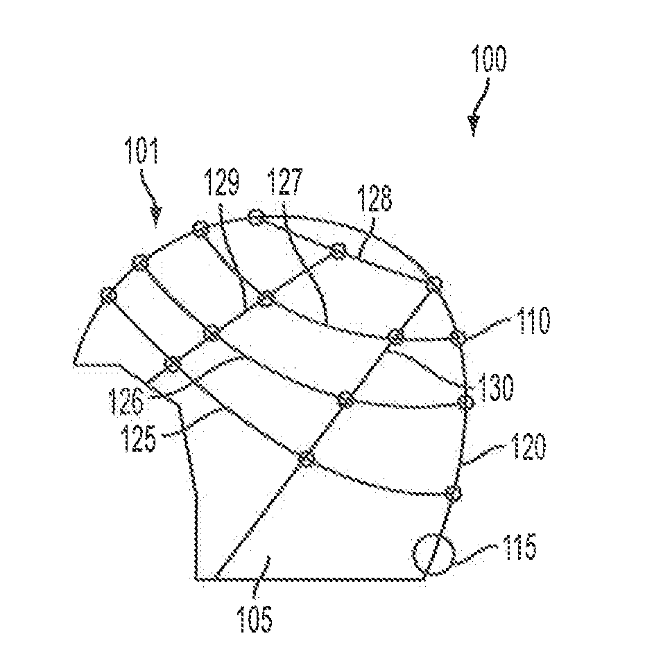
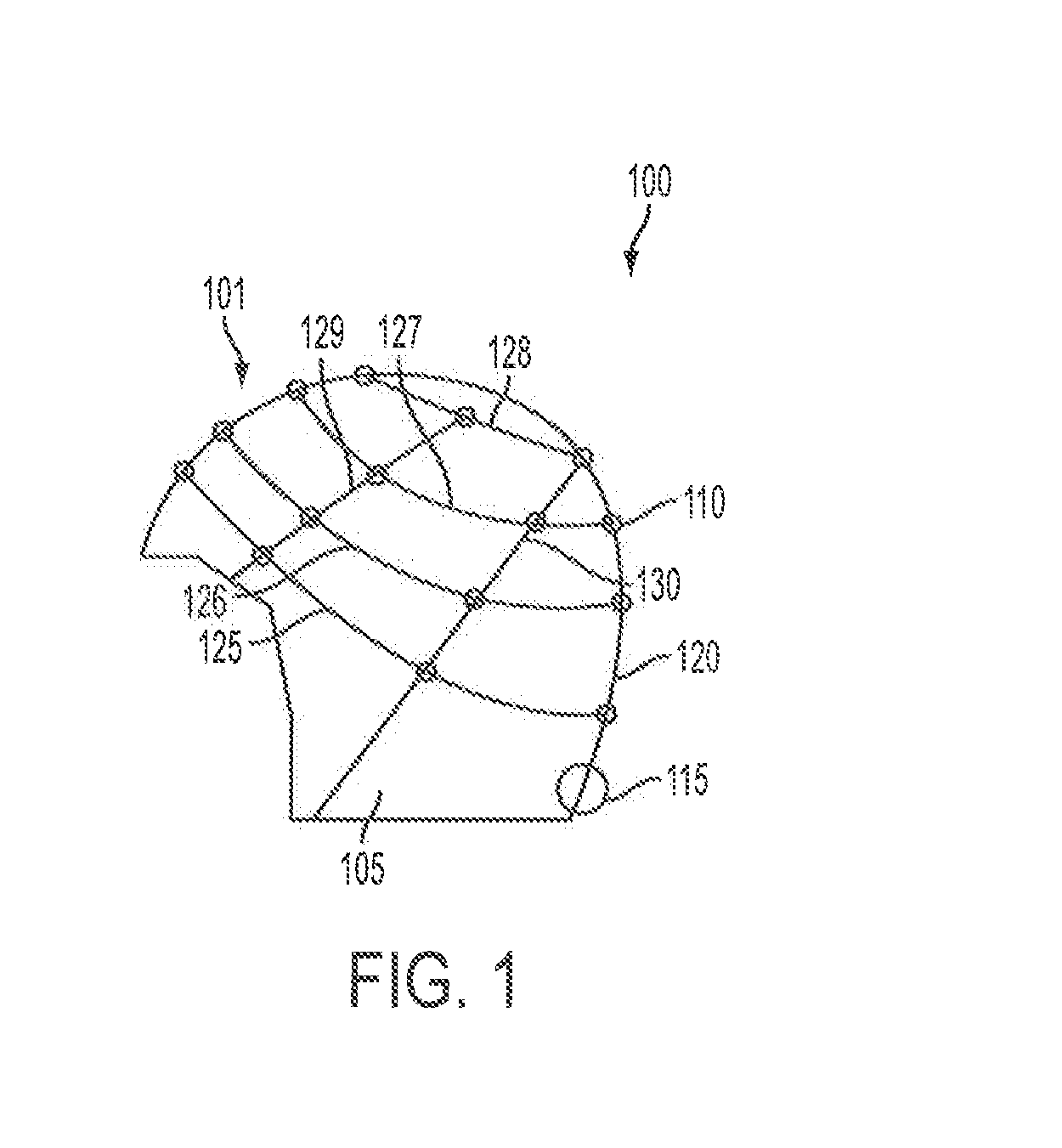
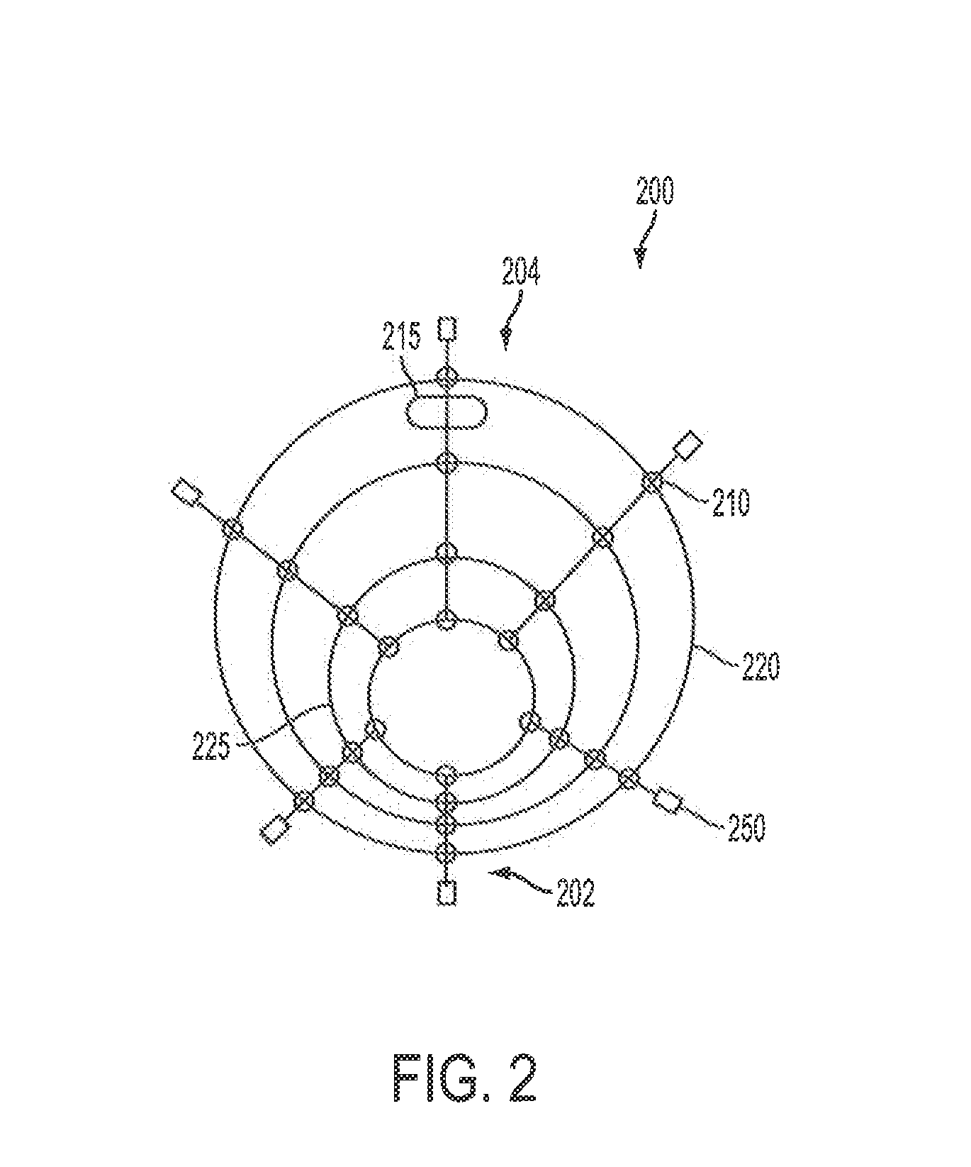
The present invention is related to an illuminated helmet cover which has an illuminating element that can be lit up. The helmet cover includes a strand that is connected to the illuminating element and is designed to go around the helmet. A connecting component engages with the strand and the helmet to hold them together. The helmet cover also has a power source that engages with the helmet to provide power to the illuminating element. The illuminating element is electrically connected to the conductive material. The helmet cover can be easily placed around the helmet and securely attached using a clamp or wire. The technical effect of this invention is to provide an illuminated helmet cover that is convenient and easy to use.

Problems solved by technology

However, both manual cycling and motorized cycling inherently include significant safety risks for those individuals participating in them, especially when cycling upon busy roadways that are also used by the more common, and heavier, trucks and automobiles.
In a collision, a rider upon a bicycle or, motorized cycle is in a much greater risk of injury or death due to the relative lack of protection for the rider's body.
Many such collisions result from the riders of bicycles or other motorized cycles not being seen by other users on the roadway.
This is often the case because bicycles and other motorized cycles are much less common on roadways so other drivers have not been conditioned to looking for these smaller vehicles.

Method used


Image

  • Illuminating helmet cover
  • Illuminating helmet cover
  • Illuminating helmet cover

Examples


Embodiment Construction

[0024]The detailed description of exemplary embodiments herein makes reference to the accompanying drawings and pictures, which show the exemplary embodiment by way of illustration and its best mode. While these exemplary embodiments are described in sufficient detail to enable those skilled in the art to practice the invention, it should be understood that other embodiments may be realized and that logical and mechanical changes may be made without departing from the spirit and scope of the invention. Thus, the detailed description herein is presented for purposes of illustration only and not of limitation. For example, the steps recited in any of the method or process descriptions may be executed in any order and are not limited to the order presented. Moreover, any of the functions or steps may be outsourced to or performed by one or more third parties. Furthermore, any reference to singular includes plural embodiments, and any reference to more than one component may include a s...


PUM


Abstract

An illuminating helmet cover configured to connect with a helmet, such as a motorcycle helmet, bicycle helmet, construction helmet, or the like. The illuminating helmet cover includes a plurality of illuminating elements, such as light-emitting diodes, lamps, or reflective surfaces, which allow a user to be more easily visible. The plurality of illuminating elements are coupled with one or more strands that are configured to extend over the helmet, such as in the form of a netting. The illuminating helmet cover fastens with the helmet via one or more coupling components, such as clamps, hooks, adhesives, Velcro, etc. A power source is connected with the one or more strands for providing power to one or more of the plurality of illuminating elements. Operation of the plurality of lights may he customized by the user, for example, by changing colors, strobe patterns, and / or brightness or intensity.

Description

CROSS REFERENCE TO RELATED APPLICATIONS[0001]This application claims the benefit of U.S. Provisional Patent Application Ser. No. 61 / 930,924, filed on Jan. 23, 2014, entitled ILLUMINATED HELMET COVER,” which is hereby incorporated by reference in its entirety.BACKGROUND[0002]1. Field of the Invention[0003]The present invention relates to a method and system for visually illuminating apparel or equipment worn by a user. More particularly, the present invention relates to an illuminated cover or netting that is configured to fasten to motorcycle, bicycle, or other helmets for providing improved safety to the user.[0004]2. Description of the Related Art[0005]Cycling is a popular outdoor activity that is enjoyed by a wide percentage of the world population. Not only does the activity allow users to engage in an athletic activity outside of their home for fitness or exercise purposes, but also allows individuals to easily travel from one geographic location to another without consuming th...

Claims


Application Information

Patent Timeline
IPC IPC(8): A42B3/04F21L4/02H05B33/08F21L4/08G02B5/136A42B3/00F21L4/06H05B44/00
CPCA42B3/044A42B3/003F21L4/02H05B33/0857F21L4/08G02B5/136H05B33/0845F21L4/06G02B27/017G02B27/0176F21Y2115/10F21V33/0008H05B45/20
Inventor DAS, AYSHETA
Owner DAS AYSHETA
Learn More