Microprocessor enabled article of illuminated footwear with wireless charging

a wireless charging and microprocessor technology, applied in the field of accessories and systems for illuminating footwear, can solve the problems of insufficient safety protection or other benefits of visibility, inconvenient installation, and inability to meet the needs of users, and achieve the effects of reducing the cost of installation, and increasing the cost of installation

Active Publication Date: 2010-09-14
NIKE INC
View PDF11 Cites 65 Cited by
  • Summary
  • Abstract
  • Description
  • Claims
  • Application Information

AI Technical Summary

Benefits of technology

[0008]The invention is disposed on an article of footwear and can provide the safety of a high-visibility light source in environments where the wearer is at risk of injury. As such, some potential footwear embodiments include performance running and walking shoes, cycling shoes, skateboarding shoes, and work boots. The invention disclosed and claimed herein can also be used for aesthetic purposes rather than, or in addition to, safety purposes.

Problems solved by technology

However, these applications have been limited in color change, transition effect, crossfade functionality, durability, safety, convenience, and sophistication.
A shortcoming of the former approach is that the light element is not activated when the wearer is stationary, thus affording no safety protection or other benefits of visibility.
Shortcomings of the latter approach are the added bulk of a larger and heavier battery, and the need for frequent replacement.
Further, the aforementioned disadvantages concerning the power source have prevented the incorporation of more sophisticated processing technologies and the corresponding gains in functionality, such as user-selected color changes or transition effects, due to the increased power requirements of these advantageous features.
Even further, the disadvantages concerning the power source in the higher end of power consumption have prevented the design of a fully-encapsulated electronic and battery module that is substantially impervious to the elements, due to the need for either battery replacement or the insertion of a power jack with conductive terminals.
These difficulties have also hindered the design of an electronic and battery module that is non-obtrusive, lightweight, safe, and biomechanically sound.

Method used


Image

  • Microprocessor enabled article of illuminated footwear with wireless charging
  • Microprocessor enabled article of illuminated footwear with wireless charging
  • Microprocessor enabled article of illuminated footwear with wireless charging

Examples


Embodiment Construction

[0017]Certain terminology is used in the following description for convenience only and should not be construed as limiting. The word “a” as used in the claims and in the corresponding portions of the Specification means “one or more than one.” In the drawings, the same reference numerals are employed for designating the same elements throughout the figures.

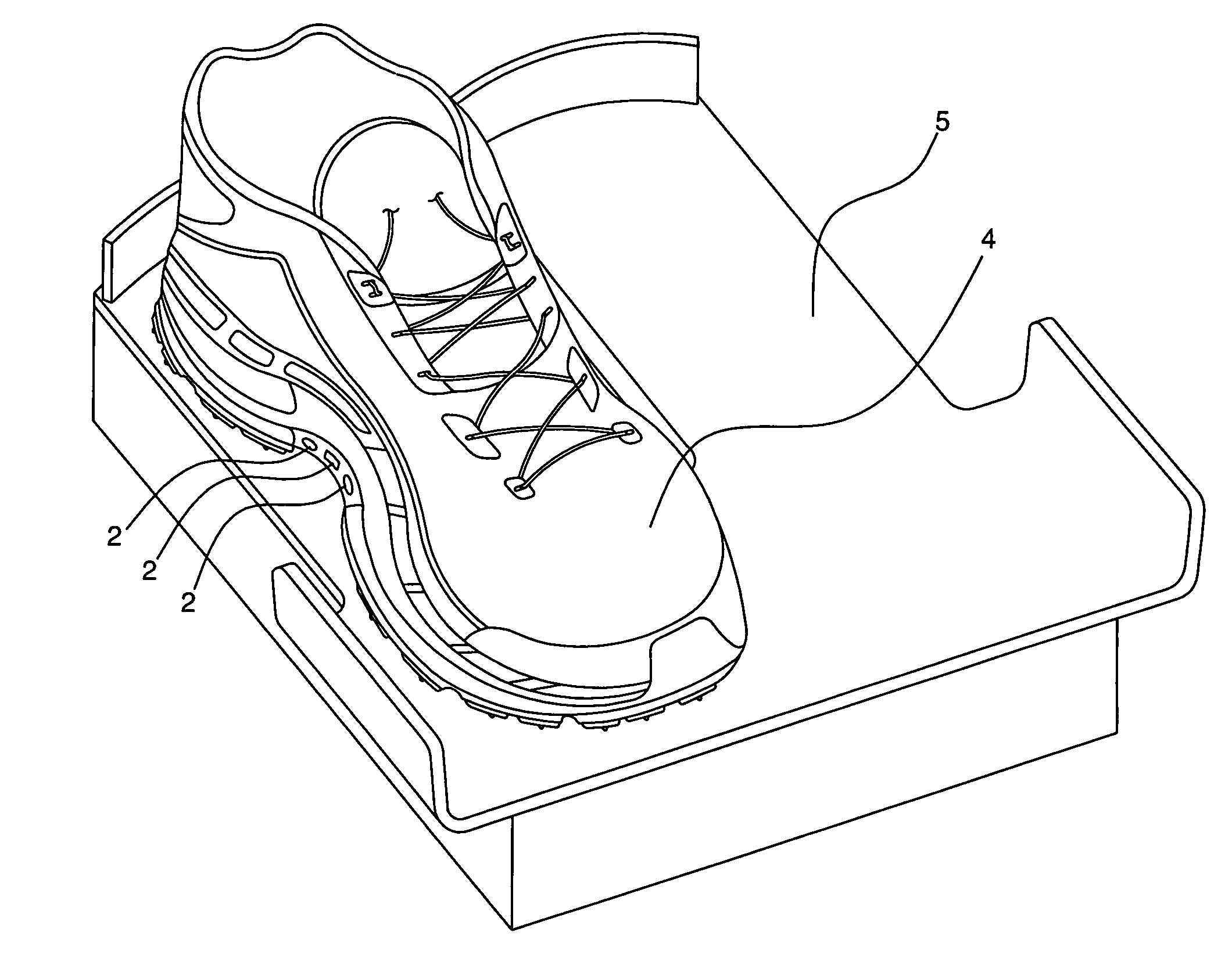
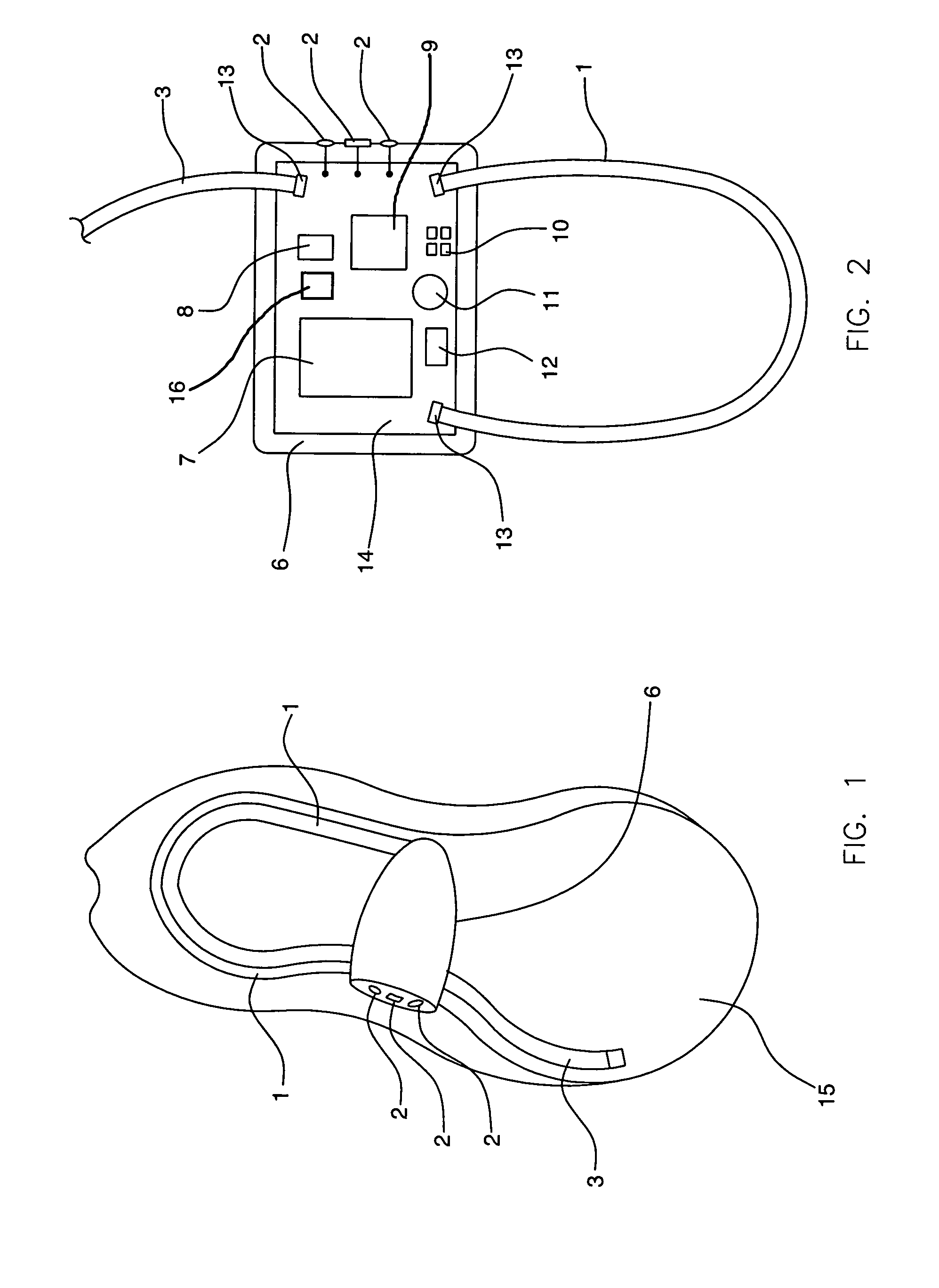
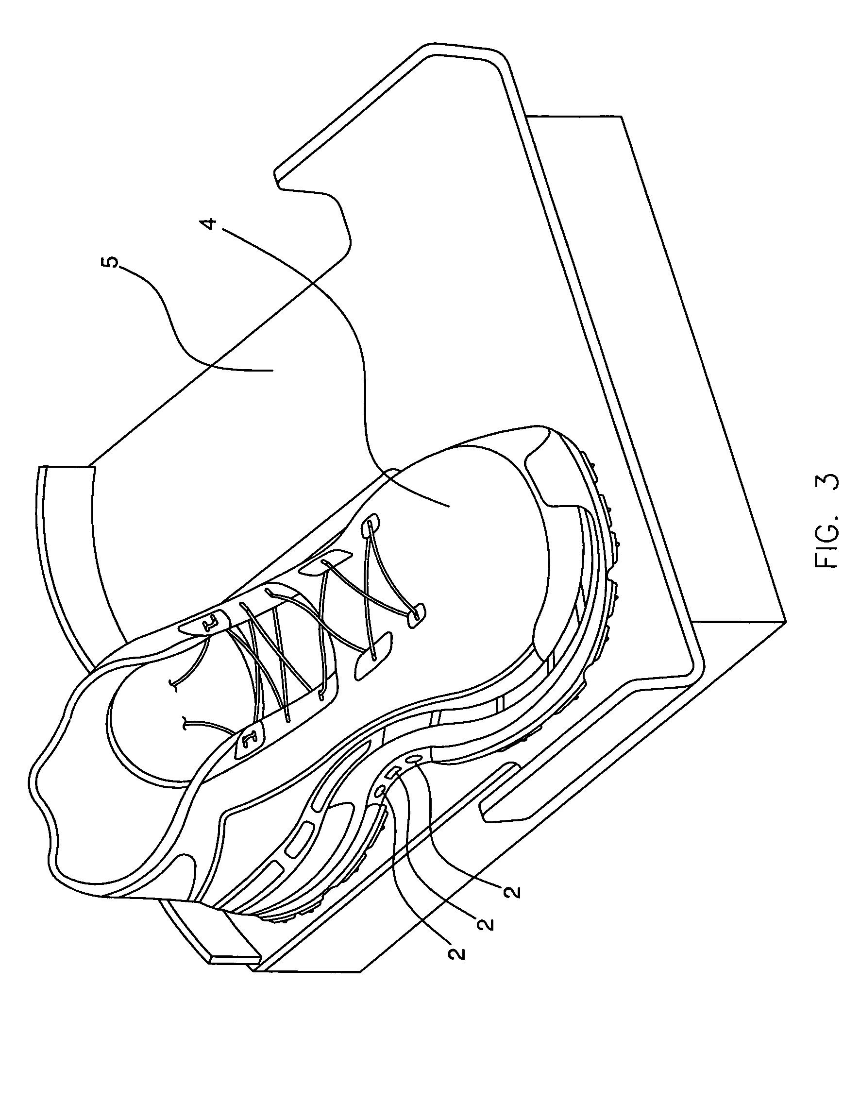
[0018]FIG. 2 shows a preferred embodiment of the electronics module that serves as the processing and power center for the inputs and outputs that are disposed on the shoe or within the electronics module itself. Preferably, the electronics module housing 6 will be composed of a protective material, such as molded plastic, that hermetically seals all the components and provides a durable, water-resistant, and impact-resistant solution for surviving the rigors of the footwear application. The protective encapsulate will also add to the safety of the final product by isolating the power source 7 from contact with the wearer's foot ...


PUM


Abstract

An apparatus and system for incorporating a resilient source of high-visibility illumination into an article of footwear. A biomechanically-sound and hermetically-sealed electronics module contains a microprocessor, power source, and at least one light source, such as a light emitting diode, or LED. The LEDs are not externally visible, but rather illuminate a diffusive substrate that is incorporated into the construction of the footwear, allowing for visibility from substantially every angle above the bottom of the sole. A control panel enables the wearer to turn the power on and off, change colors, rotate through transition effects, and the like. A charging pad allows for the wireless and contact-less recharging of the onboard power source.

Description

CROSS REFERENCE TO RELATED APPLICATIONS[0001]This application claims the benefit of U.S. Provisional Application No. 61 / 025,401 filed Feb. 1, 2008.BACKGROUND OF THE INVENTION[0002]The present invention relates generally to an apparatus and system for illuminating footwear, and more particularly, to an electronic control circuit for powering light-emitting elements disposed within shoes. Articles of footwear have been known to incorporate light-sources such as light emitting diodes (LEDs) and electroluminescent materials to either adorn the shoe with an intermittent flash of light or a static, continuous glow. However, these applications have been limited in color change, transition effect, crossfade functionality, durability, safety, convenience, and sophistication.[0003]It is also known in the art to incorporate a power source into an article of footwear to activate the light-emitting elements. See, for example, U.S. Pat. No. 6,837,590 (Marston). On the lower end of power consumpti...

Claims


Application Information

Patent Timeline
Patent Type & Authority Patents(United States)
IPC IPC(8): F21V21/08
CPCA43B3/0005A43B3/001A43B3/36A43B3/34
Inventor GALICA, MATTHIAS JOSEPHTEMKIN, ELLIOTT
Owner NIKE INC
Why Eureka
Try Eureka