Assay device with timer function

a timer function and solid phase assay technology, which is applied in the direction of biomass after-treatment, analysis using chemical indicators, instruments, etc., can solve the problems of not being able to adjust the time elapsed, and not being able to be readily done, so as to reduce the shelf life of the device

Inactive Publication Date: 2006-03-28
PHADIA AB
View PDF12 Cites 61 Cited by
  • Summary
  • Abstract
  • Description
  • Claims
  • Application Information

AI Technical Summary

Benefits of technology

[0021]Indicator substances capable of hydration, such as the cobalt dichloride hexahydrate mentioned above, if necessary together with a hygroscopic substance, may also serve as a test that the assay device is viable, since in case of leakage of moisture into the device, which reduces the shelf-life of the device, the indicator substance will change colour. Another example of a time indicator that also will indicate leakage of moisture within the device or from exposure to the exterior is a dry powder mixture consisting of (i) an easily soluble coloured substance, such as the patent blue mentioned above, (ii) a white filler substance in a proportion that gives the powde

Problems solved by technology

The timing control of EP-A-915 336, however, only indicates that flow through the flow matrix has taken place and does not provide for any adjustment of the time elapsed from the start of the assay until the colour is visible in the v

Method used


Image

  • Assay device with timer function
  • Assay device with timer function

Examples


Embodiment Construction

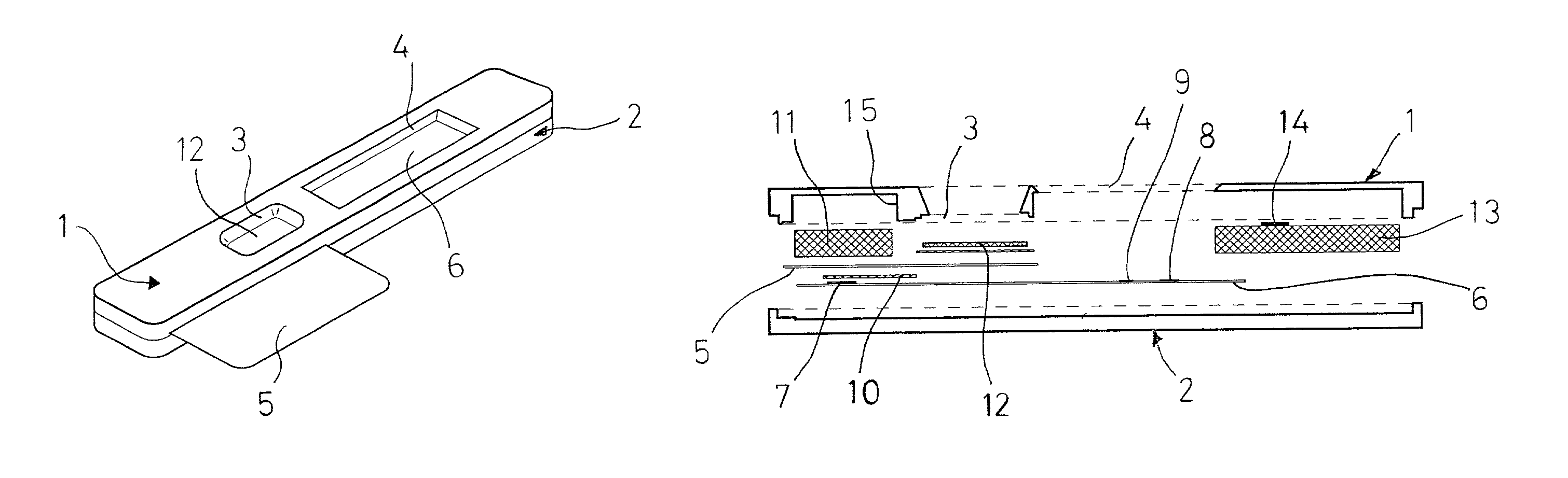
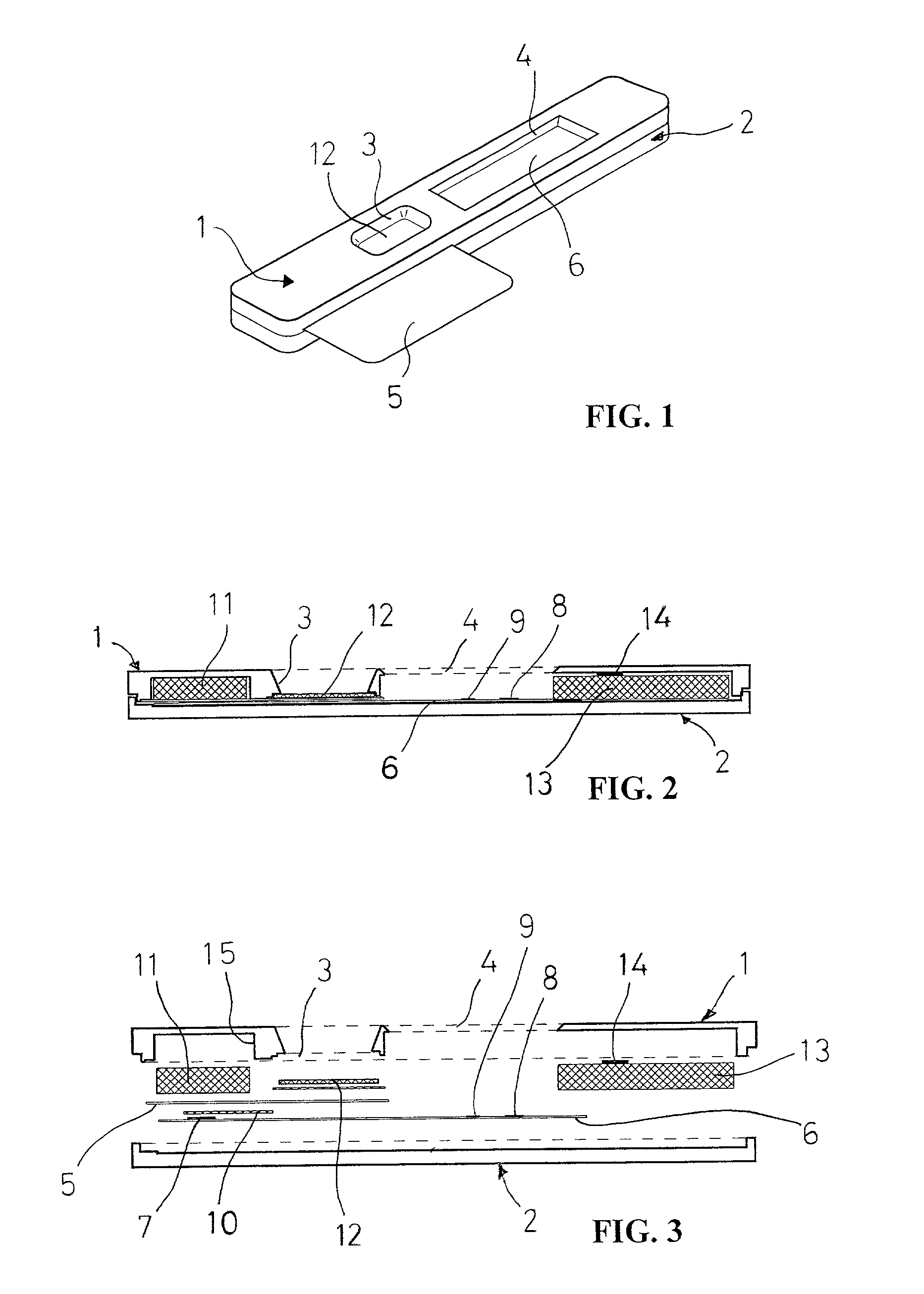
[0029]The assay device according to the present invention is provided with a time indicator that exhibits a colour change when the applied sample or other assay liquid reaches a defined position on a wicking member placed at the end of the flow matrix. In the following, the invention is illustrated applied to an assay device described in our co-pending Swedish patent application No. 9904175-8.

[0030]As best shown in FIG. 1, the device illustrated in FIGS. 1 to 3 comprises an upper housing part 1 and lower housing part 2 of a material which is inert with respect to the sample and any reagents used in the assays to be conducted with the device, e.g. polystyrene or polypropylene. The upper housing part 1 has a sample well aperture 3 (here conical) and a detection window 4. Also shown in FIG. 1 is a removable separation means 5 to be described below.

[0031]With reference now to FIGS. 2 and 3, the lower housing part 2 has mounted therein a membrane strip 6 of bibulous material (i.e. a poro...


PUM


Abstract

An assay device for determining an analyte in an aqueous sample comprises: (i) an elongate flow matrix (6) allowing lateral transport of fluid therethrough by capillary action, wherein the matrix comprises a liquid application zone (3) and downstream thereof, a detection zone (8) having an immobilized capture agent capable of directly or indirectly binding to said analyte, (ii) a wicking member (13) placed at the downstream end of the flow matrix and having an upstream end and a downstream end, and (iii) a time indicator (14) placed downstream of the detection zone (8) for indicating when liquid applied to the liquid application zone has reached the time indicator. The time indicator comprises an indicator substance or substance combination which is capable of exhibiting a visible color change when hydrated by the aqueous sample. The assay device is characterized in that the time indicator (14) is arranged in contact with the wicking member (13) at a variable position between the upstream and downstream ends thereof to thereby permit variation of the time elapsing from the application of the liquid until the indicator substance changes color. A method of performing an assay for determining an analyte in a sample, comprises the steps of flowing sample and assay liquid(s) through the flow matrix of the device such that they reach the detection zone in a predetermined sequence, and when the time indicator has changed color, reading the result of the assay in the detection zone.

Description

[0001]This application claims benefit of Provisional Application No. 60 / 206,780 filed May 24, 2000.FIELD OF THE INVENTION[0002]The present invention relates to a solid phase assay device comprising a timer function, and to a method of using the device.BACKGROUND OF THE INVENTION[0003]A type of solid phase assay devices comprises a plate-shaped flow matrix of bibulous material, usually a membrane strip, such as of cellulose nitrate or glass fiber, in which liquid can be transported laterally (i.e. in the plane of the strip) by capillary forces in the membrane. The membrane usually has a sample application zone, and a detection zone downstream of the sample application zone. In the detection zone, usually a capturing reagent for the analyte is immobilized. To conduct an assay, the application zone is contacted with the liquid sample to be assayed for the analyte of interest. The device is maintained under conditions sufficient to allow capillary action of liquid to transport the analy...

Claims


Application Information

Patent Timeline
IPC IPC(8): G01N33/53G01N33/558
CPCG01N33/558Y10S435/81Y10S436/805Y10S435/805Y10S436/81Y10S435/97
Inventor MENDEL-HARTVIG, IBUNGER, ERIK
Owner PHADIA AB
Why Eureka
Try Eureka