Electrical signal measurement
a technology of electrical signal and measurement apparatus, applied in the direction of reference comparison, automatic balancing arrangement, instruments, etc., can solve the problems of hall current probe liable to non-linearity and temperature drift, loss of measurement accuracy in a shunt of ordinary temperature coefficient of resistance, and lack of reliance on the known precision of current sensor
- Summary
- Abstract
- Description
- Claims
- Application Information
AI Technical Summary
Benefits of technology
Problems solved by technology
Method used
Image
Examples
first embodiment
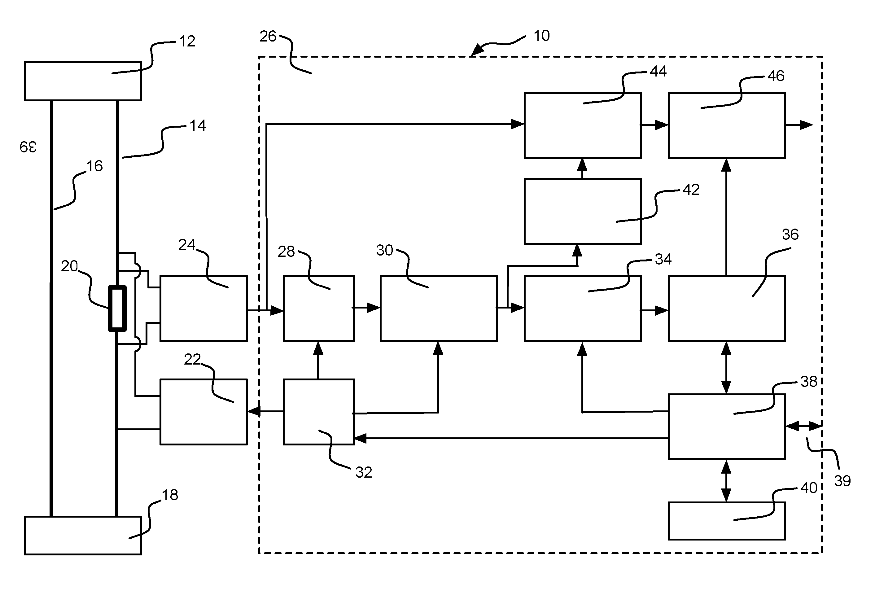
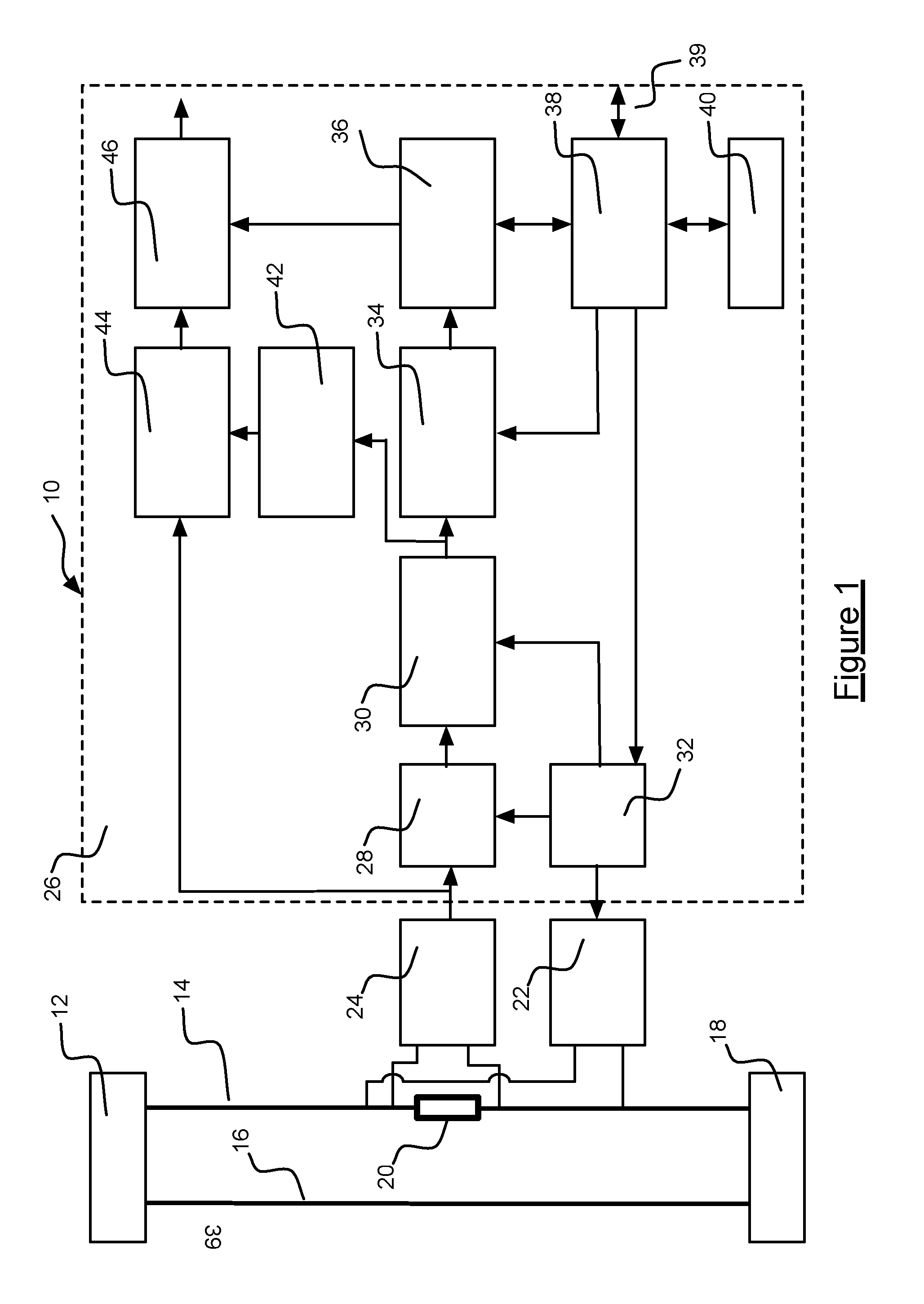
[0064]A block diagram representation of electrical measurement apparatus is shown in FIG. 1. The electrical measurement apparatus has the form of current measurement apparatus 10 which forms part of the like of a 100 A capable electricity consumption meter (not shown) installed at a point of supply to residential or business premises. A single phase mains alternating current electricity source 12 with live 14 and neutral 16 supply wires are shown in FIG. 1. Energy consuming apparatus at the residential or business premises is represented by a load 18. The current measurement apparatus 10 comprises a shunt resistor 20 (which constitutes a current sensor) in the live supply wire 14 in series with the load 18 between the load and the electricity supply 12. The shunt resistor 20 presents a low value of resistance, such as a resistance of 200 uΩ. The shunt resistor 20 is formed from a length of electrical wire, a length of conductive track on a printed circuit board, a discrete component...
second embodiment
[0077]A block diagram representation of the present invention 130 is shown in FIG. 4. Components of the current measurement apparatus 130 of FIG. 4 in common with FIG. 1 are designated with like reference numbers and the reader's attention is directed to the description provided above with reference to FIG. 1 for a description of such common components. The current measurement apparatus 130 of FIG. 4 further comprises a second shunt resistor 132 and a second voltage measuring apparatus 134. No reference input signal is applied to the second shunt resistor 132 whereby the output signal from second voltage measuring apparatus 134 comprises the electrical output signal but lacks the reference output signal. The current measurement apparatus 130 yet further comprises a subtraction component 136 which is operative to subtract the output signal from the second voltage measuring apparatus 134 from the output signal from the first voltage measuring apparatus 24. The subtraction component 13...
third embodiment
[0078]A block diagram representation of electrical measurement apparatus is shown in FIG. 5. The electrical measurement apparatus has the form of voltage measurement apparatus 150 which is configured to measure the line voltage between the live and the neutral conductor of an AC system. The electrical measurement apparatus 150 forms part of the like of a 100 A capable electricity consumption meter (not shown) installed at a point of supply to residential or business premises. A single phase mains alternating current electricity source 12 with live 14 and neutral 16 supply wires are shown in FIG. 5. Energy consuming apparatus at the residential or business premises is represented by a load 18. The electrical measurement apparatus 150 comprises a first resistor 154 in series with a second resistor 152 (which together constitute a potential attenuator) between the live conductor 14 the neutral conductor 16. The electrical measurement apparatus 150 further comprises a signal source 162 ...
PUM
 Abstract
Description
Claims
Application Information
 - R&D
- Intellectual Property
- Life Sciences
- Materials
- Tech Scout
- Unparalleled Data Quality
- Higher Quality Content
- 60% Fewer Hallucinations
Browse by: Latest US Patents, China's latest patents, Technical Efficacy Thesaurus, Application Domain, Technology Topic, Popular Technical Reports.
© 2025 PatSnap. All rights reserved.Legal|Privacy policy|Modern Slavery Act Transparency Statement|Sitemap|About US| Contact US: help@patsnap.com


