Head mounted display device, control method for head mounted display device, and computer program

a display device and display device technology, applied in the field of head mounted display devices, can solve the problems of device not including image display units, device not including or not including, and user fatigue,

Active Publication Date: 2016-06-02
SEIKO EPSON CORP
View PDF6 Cites 5 Cited by
  • Summary
  • Abstract
  • Description
  • Claims
  • Application Information

AI Technical Summary

Benefits of technology

[0007]An advantage of some aspects of the invention is to solve the proble...

Problems solved by technology

As disclosed in JP-A-2011-205195, when significantly changing the convergence angle of the user, there has been a problem in that a tired feeling is g...

Method used


Image

  • Head mounted display device, control method for head mounted display device, and computer program
  • Head mounted display device, control method for head mounted display device, and computer program
  • Head mounted display device, control method for head mounted display device, and computer program

Examples


first embodiment

A. First Embodiment

A-1. Configuration of a Head Mounted Display Device

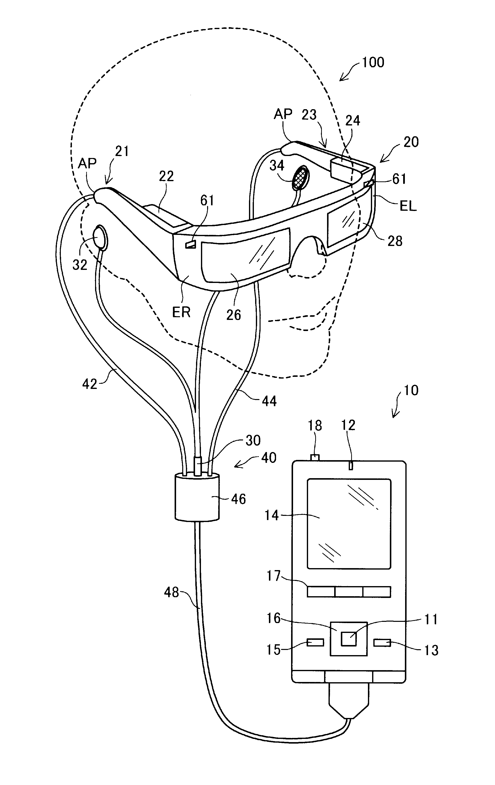
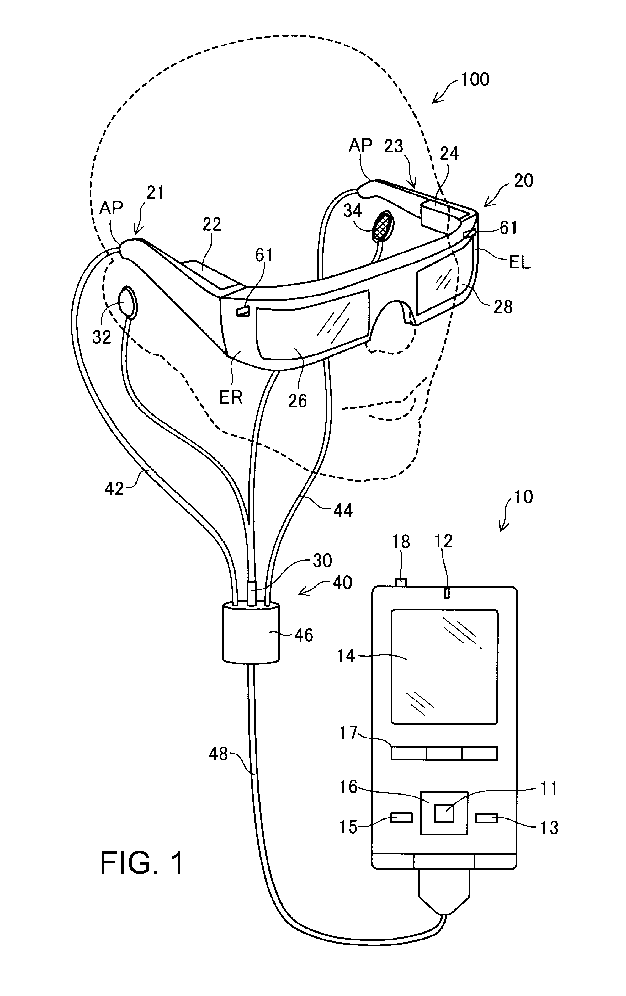
[0033]FIG. 1 is an explanatory diagram illustrating an external configuration of a head mounted display device 100 (HMD 100). The HMD 100 is a display device mounted on a head and is also called a head mounted display. The HMD 100 in the present embodiment is an optical transmission type head mounted display device with which the user can directly and visually recognize an outside scene when the user visually recognizes a virtual image. In the present specification, the virtual image visually recognized by the user by the HMD 100 is also called “display image” for convenience.

[0034]The HMD 100 includes the image display unit 20 that causes the user to visually recognize the virtual image in the state of being mounted on the user's head and a controller 10 that controls the image display unit 20.

[0035]The image display unit 20 is a mounting body to be mounted on the user's head and has a glasses shape in the presen...

modification example

B. Modification Example

[0085]The invention is not limited to the embodiment described above and various aspects can be embodied without departing from the spirit thereof. For example, the following modification can also be possible.

modification example 1

B-1. Modification Example 1

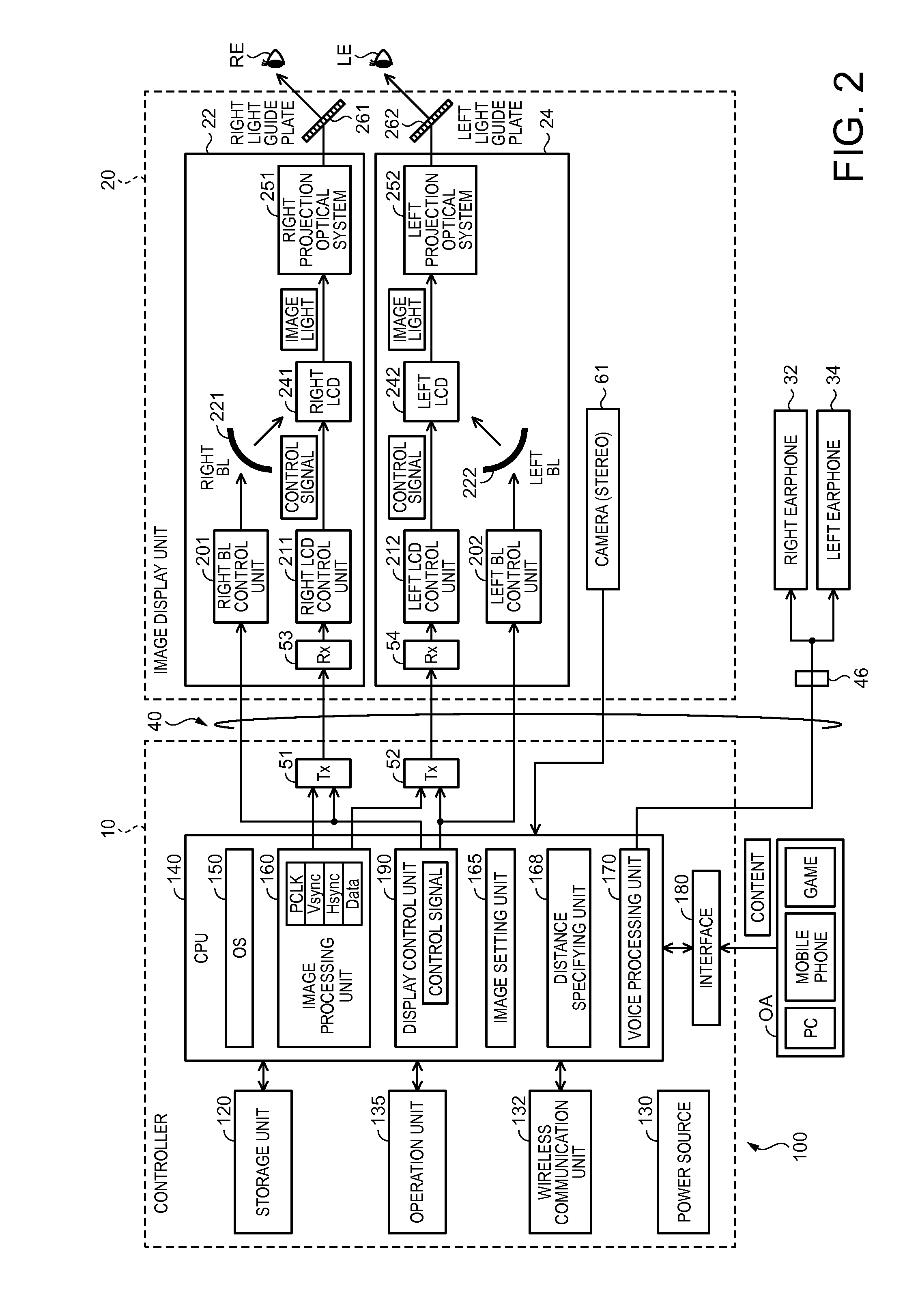
[0086]FIG. 9 is a block diagram functionally illustrating a configuration of the HMD 100a in a modification example. In the modification example, a measuring method for distance to a subject existing at a specific position in the outside scene SC is different from that in the embodiment described above, and other configurations are the same as that in the embodiment described above. As illustrated in FIG. 9, in the image display unit 20a in the modification example, a right eye image capturing camera 67 and a left eye image capturing camera 69 are included. The right eye image capturing camera 67 captures an image of a right eye RE of the user who wears the image display unit 20a and the left eye image capturing camera 69 captures an image of a left eye LE of the user. Differently from that in the embodiment described above, a distance specifying unit 168a specifies the position where the user is visually recognizing based on the image of the right eye RE ...


PUM


Abstract

A transmission type head mounted display device includes a distance measuring unit that measures a distance to a specific point in an outside scene, an image display unit that is capable of transmitting the outside scene and displays an image, and an image setting unit that controls the image display unit such that the image can be stereoscopically displayed at the position of measured distance, and in a case where the measured distance is changed, sets the image stereoscopically displayed at the position of the distance measured before the change as the image to be stereoscopically displayed at the position of the distance measured after the change over a time longer than a time required for the measured distance be changed.

Description

BACKGROUND[0001]1. Technical Field[0002]The present invention relates to a head mounted display device.[0003]2. Related Art[0004]A head mounted display device (HMD) that is a display device mounted on a head is known. The head mounted display device, for example, generates an image light using a liquid crystal display and a light source, guides the generated image light to the eyes of a user using a projection optical system and a light guide plate, and causes the user to visually recognize a virtual image. Of the head mounted display device, there are two types: a transmission type device with which the user can visually recognize an outside scene in addition to the virtual image and a non-transmission type device with which the user cannot visually recognize the outside scene. There are two types of the transmission type head mounted display device: an optical transmission type head mounted display device and a video transmission type head mounted display device.[0005]In JP-A-2006...

Claims


Application Information

Patent Timeline
IPC IPC(8): H04N13/04G06T19/20G02B27/01H04N13/00
CPCH04N13/044H04N13/0022H04N13/0497G06T19/20G02B27/0172G02B2027/0185H04N2213/002G02B2027/0134G02B2027/014G02B2027/0138G02B27/0179H04N13/344G06T19/006H04N13/128H04N13/398
Inventor ARUGA, NAOTO
Owner SEIKO EPSON CORP
Why Eureka
Try Eureka