Mouthguard and fabricating method thereof

a technology of mouthguards and fabrication methods, applied in dentistry, dental prosthetics, sports equipment, etc., can solve the problems of high cost of conventional methods, drawbacks, and insatiable diversity of patterns and colors, and achieve the effect of not affecting human health

Inactive Publication Date: 2016-06-09
SHUN HSIANG PLASTIC
View PDF23 Cites 9 Cited by
  • Summary
  • Abstract
  • Description
  • Claims
  • Application Information

AI Technical Summary

Benefits of technology

[0007]The present invention provides a mouthguard with a marked pattern. According to the present invention, the possibility of peeling off the pigment or ink from the marked pattern will be minimized, and thus the use of the mouthguard is not harmful to human health.
[0008]The present invention also provides a method of fabricating a mouthguard in a simplified and cost-effective manner.

Problems solved by technology

However, the fabricating cost of the conventional method is very high, and the diversity of the pattern and color is usually unsatisfied.
However, since the mouthguard should be heated and softened to allow the mouthguard to properly fit the shape of the teeth before use, some drawbacks may occur.
Under this circumstance, the marked pattern becomes blurred, and even the peeled pigment or ink is usually harmful to the user's health.

Method used


Image

  • Mouthguard and fabricating method thereof
  • Mouthguard and fabricating method thereof
  • Mouthguard and fabricating method thereof

Examples


first embodiment

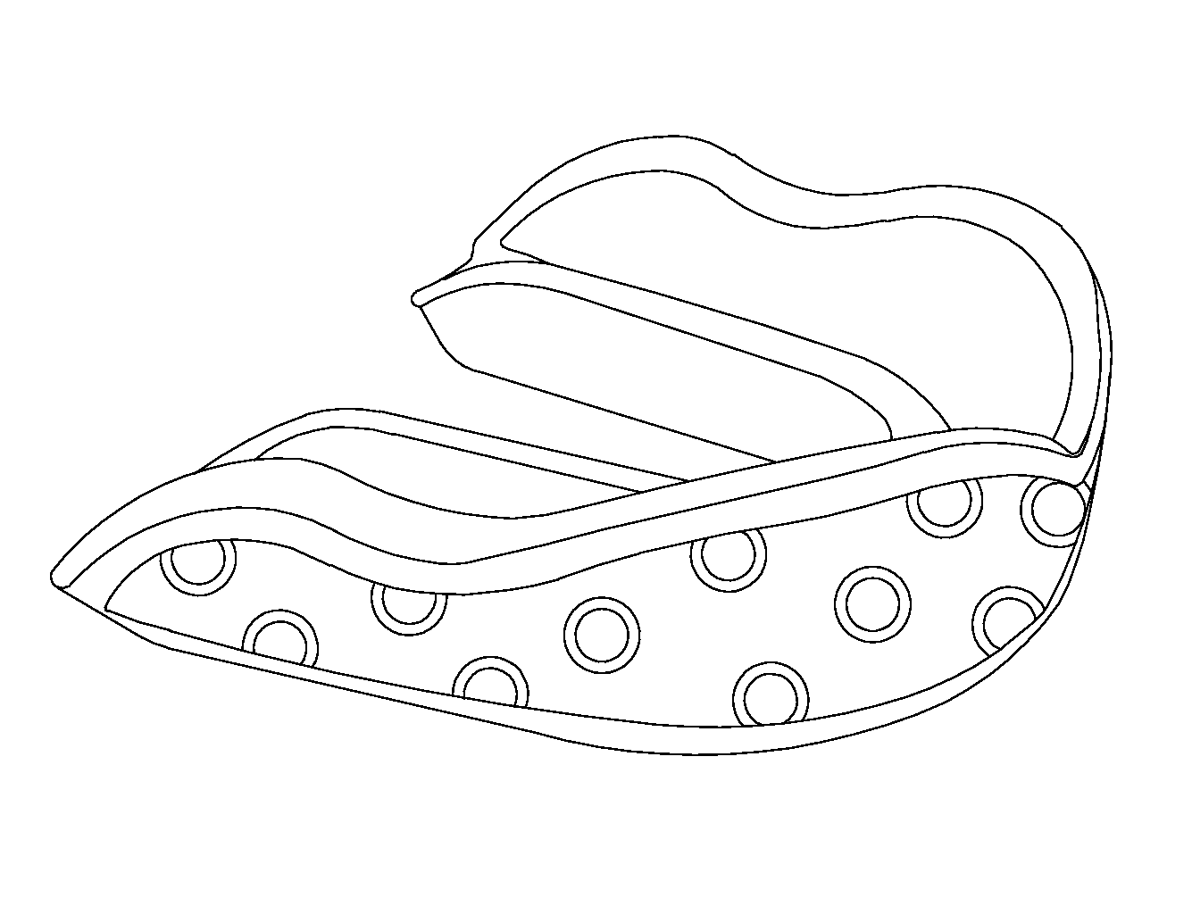
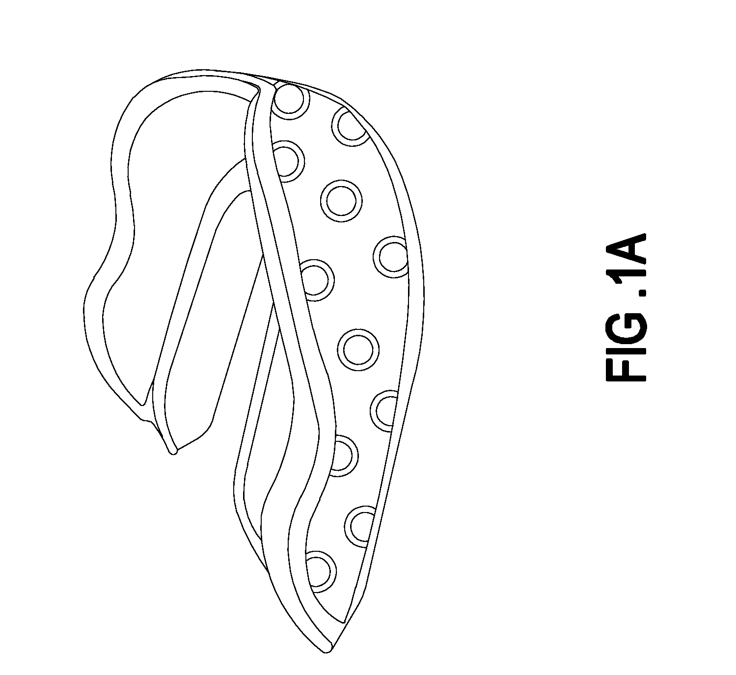
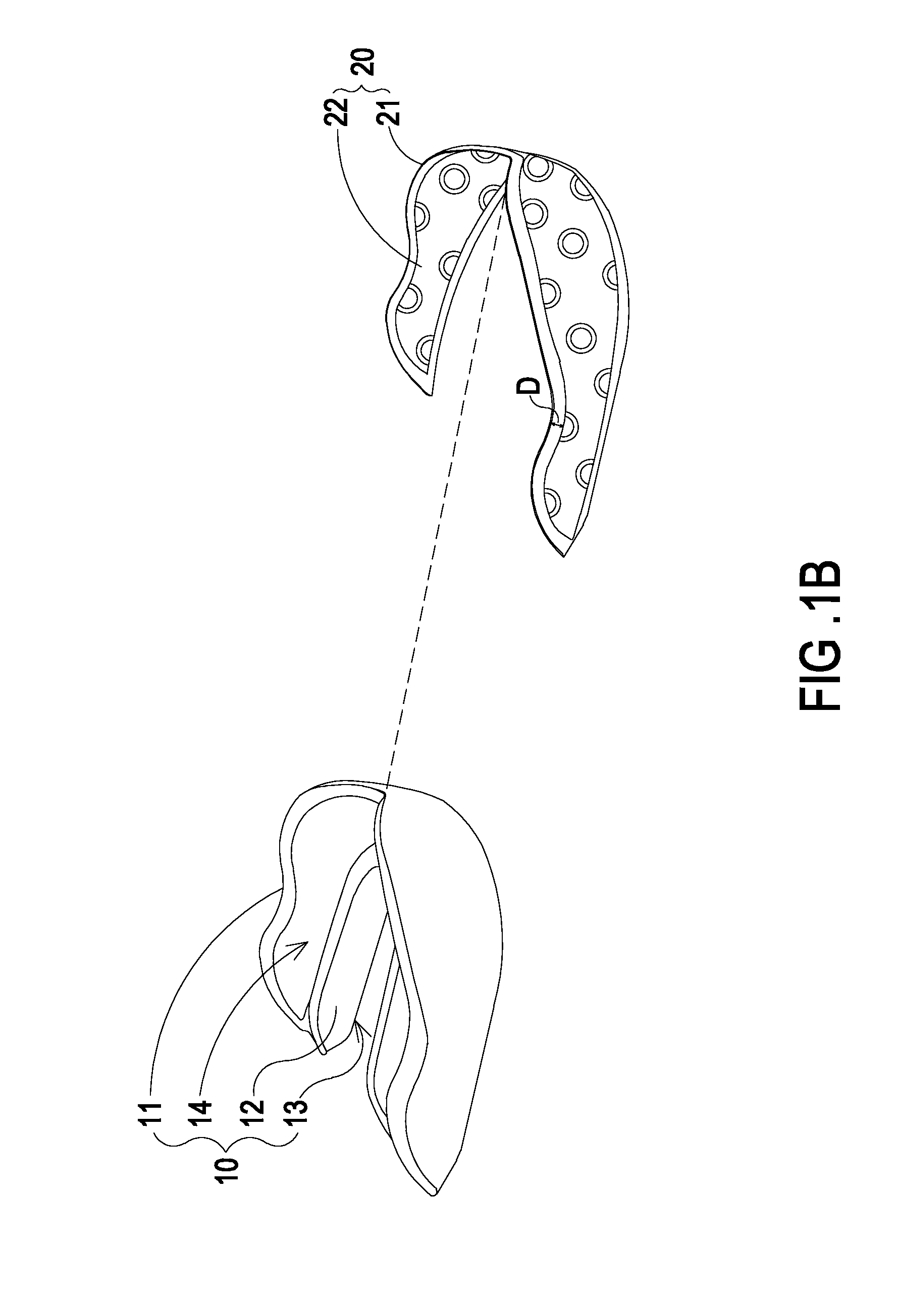
[0019]FIG. 1A is a schematic perspective view illustrating a mouthguard according to the present invention. FIG. 1B is a schematic exploded view illustrating the mouthguard of FIG. 1A. As shown in FIGS. 1A and 1B, the mouthguard comprises a mouthguard body 10 and a film structure 20 with a marked pattern. The mouthguard body 10 is substantially a U-shaped base having a shape matching the teeth.

[0020]In this embodiment, the mouthguard body 10 comprises a front part 11, a rear part 12 and a bottom part 13. Moreover, a trench 14 is defined by the front part 11, the rear part 12 and the bottom part 13 collaboratively. The trench 14 is used for accommodating the teeth. The film structure 20 has a first surface 21 and a second surface 22. A marked pattern is printed on the second surface 22. More especially, the second surface 22 of the film structure 20 is attached on an outer surface of the front part 11 of the mouthguard body 10 while the mouthguard body 10 is produced by an injection ...

second embodiment

[0030]FIG. 3A is a schematic perspective view illustrating a mouthguard according to the present invention. FIG. 3B is a schematic exploded view illustrating the mouthguard of FIG. 3A. As shown in FIGS. 3A and 3B, the mouthguard comprises a mouthguard body 10 and a three-dimensional film structure 30 with a marked pattern. In comparison with the mouthguard of FIG. 1B, the three-dimensional film structure 30 of this embodiment is distinguished. The three-dimensional film structure 30 comprises a first film 31 and a second film 34. The second film 34 is extended inwardly from a bottom periphery of the first film 31. Moreover, the size and shape of the first film 31 substantially match the size and shape of the front part 11 of the mouthguard body 10, and the size and shape of the second film 34 substantially match the size and shape of the bottom part 13 of the mouthguard body 10. The first film 31 comprises a first surface 32 and a second surface 33. The second film 34 comprises a th...

third embodiment

[0032]FIG. 3C is a schematic exploded view illustrating a mouthguard according to the present invention. In this embodiment, the three-dimensional film structure 30 further comprises a third film 37 corresponding to the rear part 12 of the mouthguard body 10. The third film 37 is extended upwardly from an inner periphery of the second film 34. The size and shape of the third film 37 substantially match the size and shape of the rear part 12 of the mouthguard body 10. The third film 37 comprises a fifth surface 38 and a sixth surface 39. The marked pattern is printed on the sixth surface 39 of the third film 37. Similarly, while the mouthguard body 10 is produced by the injection molding process, the second surface 33, the fourth surface 36 and the sixth surface 39 of the three-dimensional film structure 30 are respectively attached on the outer surfaces of the front part 11, the bottom part 13 and the rear part 12 of the mouthguard body 10. As a consequence, the ink or pigment of th...


PUM


Abstract

A mouthguard includes a mouthguard body and a film structure. The mouthguard body includes a front part, a rear part and a bottom part. A trench is defined by the front part, the rear part and the bottom part collaboratively. The film structure includes a first surface and a second surface. A marked pattern is printed on the second surface. The second surface of the film structure is attached on an outer surface of the front part of the mouthguard body while the mouthguard body is produced by an injection molding process, so that ink or pigment of the marked pattern is confined between the mouthguard body and the film structure without being exposed to outside.

Description

CROSS-REFERENCE TO RELATED APPLICATION[0001]This application is a Continuation Application of U.S. patent application Ser. No. 13 / 899,008 filed on May 21, 2013, and entitled “MOUTHGUARD AND FABRICATING METHOD THEREOF”, the entirety of which is hereby incorporated by reference.FIELD OF THE INVENTION[0002]The present invention relates to a mouthguard and a fabricating method thereof, and more particularly to a mouthguard with a marked pattern and a fabricating method thereof.BACKGROUND OF THE INVENTION[0003]A mouthguard is a flexible protective device for covering and wrapping teeth and gums in order to protect upper and lower teeth, cheeks and other tissues. Generally, the mouthguard has the functions of transferring forces and redistributing forces. The mouthguard is widely used to prevent injury in intense or contact sports such as boxing, taekwondo, sanda, wrestling, basketball, soccer, rugby, ice hockey or hockey. When an external force is exerted on the cheek and the lower face,...

Claims


Application Information

Patent Timeline
Patent Type & Authority Applications(United States)
IPC IPC(8): A63B71/08B29C45/16
CPCA63B71/085B29K2623/083B29C45/1679A63B2071/0694
Inventor LIN, CHIH-JU
Owner SHUN HSIANG PLASTIC
Why Eureka
Try Eureka