Flat-bottomed landing craft

a landing craft and flat bottom technology, applied in the field of flat bottomed landing craft, can solve the problems of carrying a very heavy load, and achieve the effect of low noise and less nois

Inactive Publication Date: 2016-06-09
LEWIS NATHANIAL HENRY
View PDF6 Cites 4 Cited by
  • Summary
  • Abstract
  • Description
  • Claims
  • Application Information

AI Technical Summary

Benefits of technology

The patented landing boat works like an Air Cushioned Landing Vehicle (ACLV). Its design reduces loudness compared to other types of boats but still produces minimal noise during operation.

Problems solved by technology

The technical problem of this patent is to design and build a fast, durable, and efficient landing craft that can carry a large amount of cargo and be easily maintained. The design should be relatively economical and easy to replace the current LCU.

Method used


Image

  • Flat-bottomed landing craft
  • Flat-bottomed landing craft
  • Flat-bottomed landing craft

Examples


Embodiment Construction

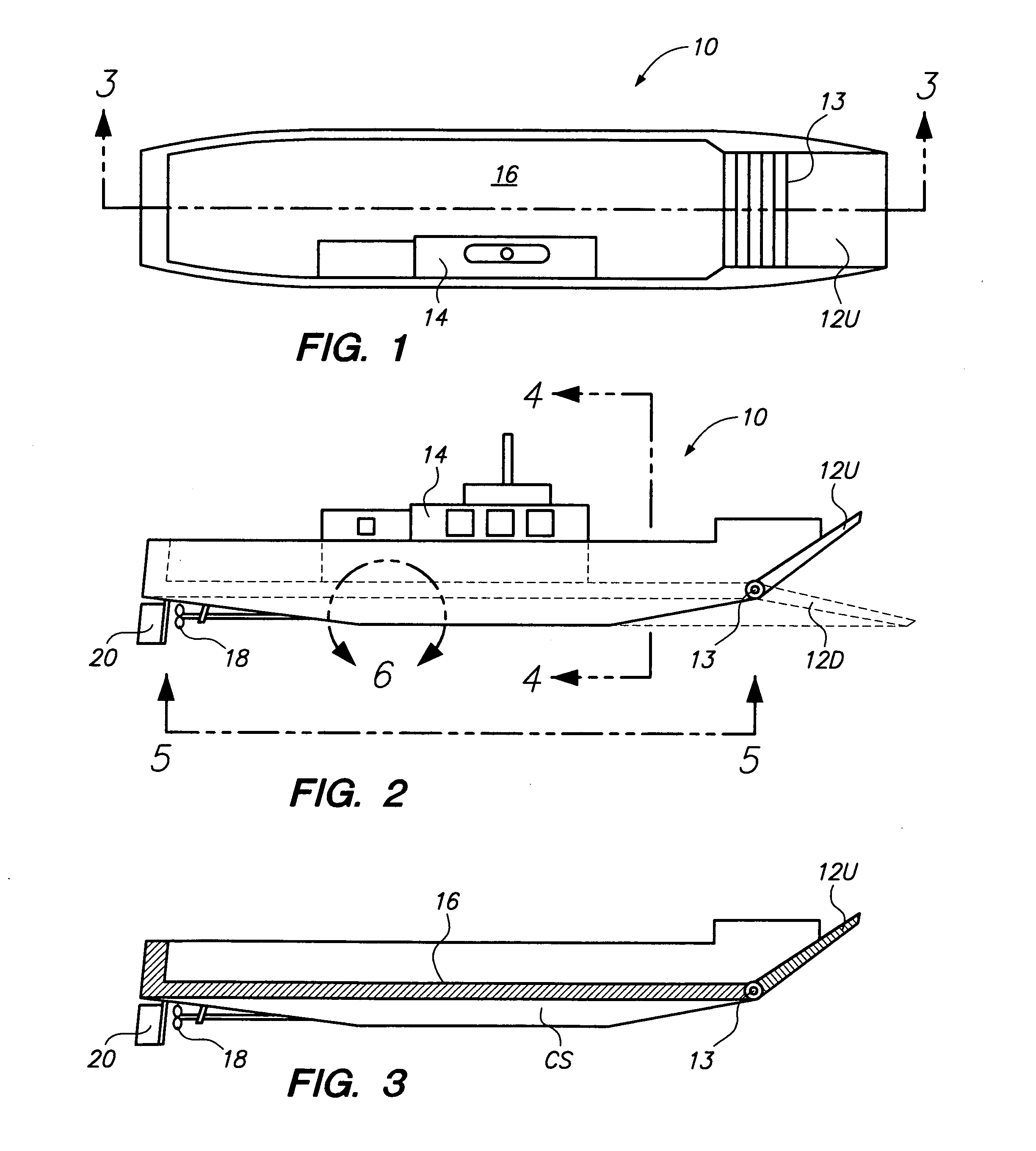
[0019]This landing craft 10 has a ramp 12U in its up position, and a hinge 13 connects it to a cargo bay 16 adjacent a control station 14; see FIG. 1.

[0020]Refer to FIG. 2. The ramp about its hinge 13 is shown in its up position 12U and its down position 12D. A side view of the control station 14, propeller 18, and rudder 20 is shown. It doesn't matter if it looks like a World War 2 landing craft, if it gets the job done.

[0021]Refer to FIG. 3. The ramp 12U and its hinge 13 are shown. A channel surface CS is seen under the cargo bay 16. Two sets of propeller 18 and rudder 20 combinations can be used at the rear, one on each side of the craft; or just one set in the middle.

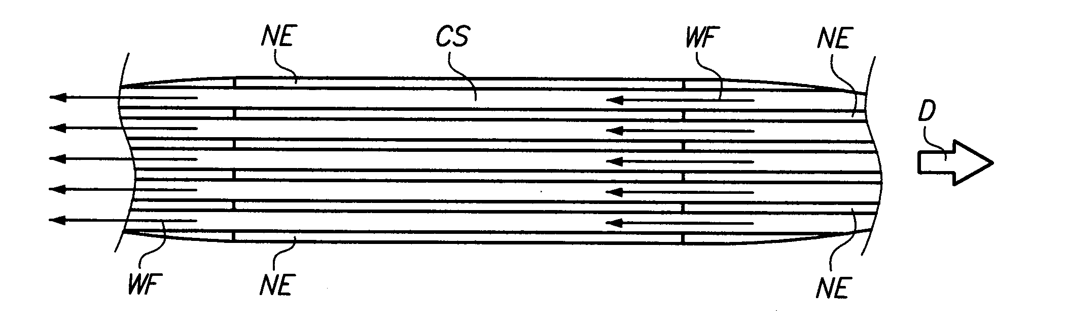
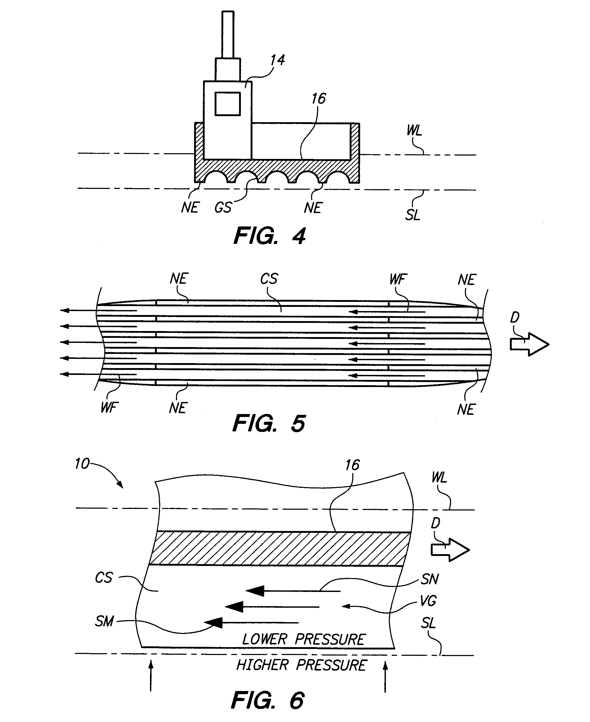
[0022]Refer to FIG. 4. The control station 14 is shown in the cargo bay 16. The water level WL shown is when the landing craft is under maximum load. The surfing layer SL is associated with the actions and effect of the narrow edges NE and channel surfaces CS, when the craft is in motion. Each channel surface CS has...


PUM


Abstract

This landing craft is capable of transporting heavy tracked and/or wheeled vehicles and troops from amphibious assault ships to beachheads or piers. A flat bottom has an unique design using Bernoulli's principle. The benefits are good speed, efficiency, durableness, and relatively economical and low noise.

Description


Claims


Application Information

Patent Timeline
Owner LEWIS NATHANIAL HENRY
Why Eureka
Try Eureka