
Conveyor system for transporting items

Inactive Publication Date: 2016-06-09
CRISPLANT
View PDF5 Cites 2 Cited by
  • Summary
  • Abstract
  • Description
  • Claims
  • Application Information

AI Technical Summary

Benefits of technology

[0004]It is an object of the present invention to provide a conveyor system of the type mentioned above which may be manufactured in an economical way with simple means, even allowing existing conveyor systems with no current efficient damping to be easily modified to provide such an efficient damping. This is achieved in that the shock-absorbing device has an upper face which is located below the at least one conveyor belt, facing the lower surfa

Problems solved by technology

However, it has been found that this dampening is usually not sufficient in order to limit wear on the items and on the conveyor system, an

Method used


Image

  • Conveyor system for transporting items
  • Conveyor system for transporting items
  • Conveyor system for transporting items

Examples


Example

DETAILED DESCRIPTION OF THE DRAWINGS

[0017]In the following description, items 104 are often referred to as totes. It should be 10 understood that the totes or items 104 referred to below may support articles, such as pieces of luggage, to be conveyed. In the embodiments of any of the drawings the articles need, however, not be supported by totes. Accordingly, in those embodiments, the totes illustrated in the drawing may be substituted by articles.

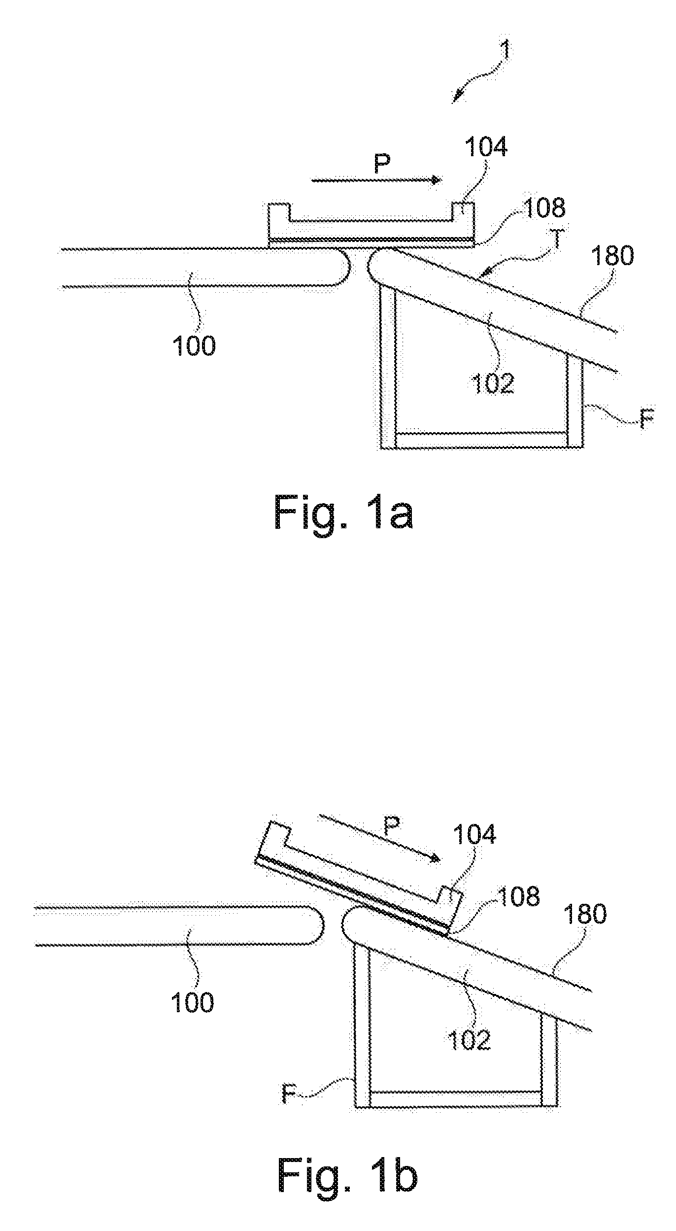
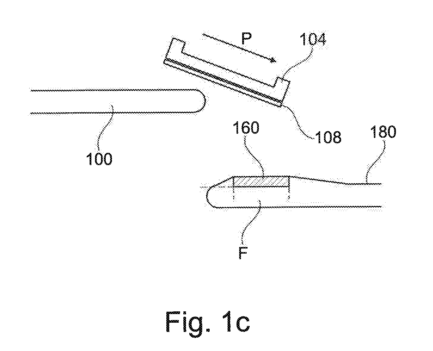
[0018]In FIG. 1a, a first and a second conveyor section 100, 102 arranged at a mutual angle in a vertical plane are illustrated. The conveyor sections 100, 102 preferably each comprise a frame F supporting an endless belt 180 for engaging a bottom surface of a tote 104 being transported from the left to the right as indicated by 20 the arrow P. As will be seen in FIG. 1b the tote 104 will tilt upon moving from one conveyor section to the next, with the front part of the tote impacting the endless belt 180 of the downstream conveyor section...


PUM


Abstract

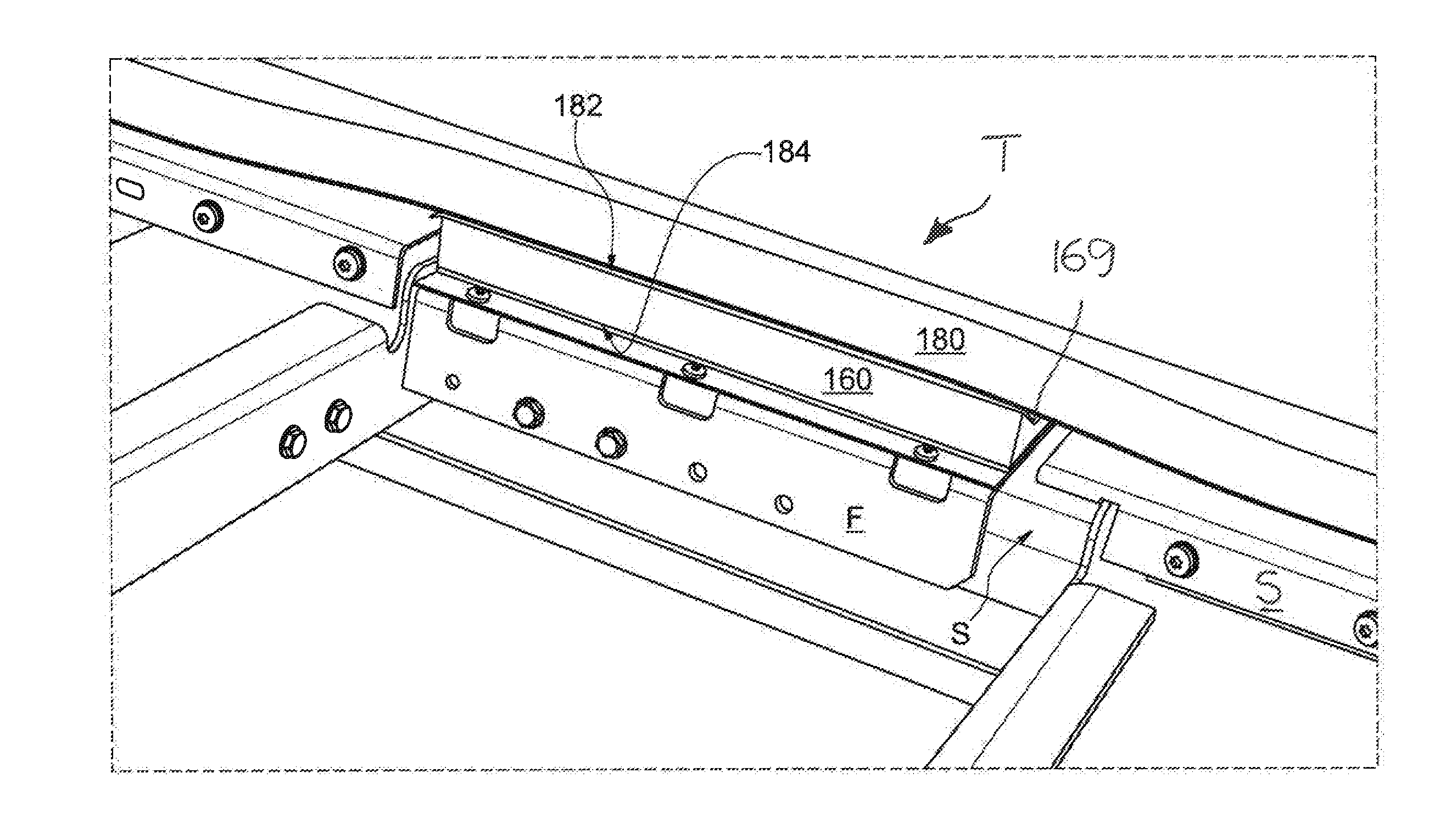
The invention relates to a conveyor system (1) for transporting items (104) in a conveying direction (P) and comprising a first conveyor section (100), a second conveyor section (102), and a frame (F) below said second conveyor section (102), said first conveyor section (100) and said second conveyor section (102) each defining a conveying surface for engaging a bottom surface (108) of said items (104) and for forward movement of said items (104) along said conveying direction (P), said first conveyor section (100) being adapted to deliver one or more of said items (104) to an item transition region (T) of said second conveyor section (102), said second conveyor section (102) including: at least one conveyor belt (180) defining said conveying surface of said second conveyor (102), and a shock-absorbing device (160) mounted to said frame (F) in said item transition region (T), characterised in said shock-absorbing device (160) having an upper face (182) located below said at least one conveyor belt (180) and facing said conveyor belt (180), said shock-absorbing device (160) being for providing a controlled vertical deceleration of said items (104) in said transition region (T) by said conveyor belt (180) being pressed against said upper face (182) by impact applied by said items (104) onto said conveyor belt (180) in said transition region (T).

Description

TECHNICAL FIELD[0001]The present invention relates to a conveyor system, in particular a conveyor system in which items are transported by means of belt conveyors, the items being optionally transported in totes. The invention is of particular use for controlling impact from such items transported between two conveyor sections which may be arranged with an angle with respect to one another or at different levels.BACKGROUND OF THE INVENTION[0002]WO 99 / 30993 discloses a conveyor system for transporting items in a conveying direction and comprising individual belt conveyor sections along which items are conveyed in totes. A first conveyor section is adapted to deliver one or more of the item(s) to a second conveyor section, the first and second conveyor sections each defining a conveying surface for supporting the items. In a practical application of the conveyor system, two consecutive conveyor sections may define a mutual angle in a vertical plane extending in parallel to the conveyi...

Claims


Application Information

Patent Timeline
IPC IPC(8): B65G47/57B65G15/62
CPCB65G15/62B65G47/57
Inventor BENTSEN, ANDERS
Owner CRISPLANT
Learn More