Mechanically-attached nosebridge element for eyewear frame

a technology of eyewear frame and nosebridge, which is applied in the direction of spectacles/goggles, spectacles/goggles, instruments, etc., can solve the problems of adding expense and brazing difficulty, parts near brazing must remain large, and the number of pieces and welds adds to the weight of the fram

Inactive Publication Date: 2001-10-18
RITTMANN JEAN V
View PDF0 Cites 2 Cited by
  • Summary
  • Abstract
  • Description
  • Claims
  • Application Information

AI Technical Summary

Benefits of technology

[0014] Eyewear, made this way: can be assembled without tools; can weigh 1 / 4 ounce (7 grams): much less than prior-art glasses; need only ten parts; flex without permanent distortion; won't disassemble with wear (as screws do); and look nice. There is no need for tiny casted metal parts, hinges, tiny screws, tapping, brazing, polishing, plating, or earpiece over-molding (or earpiece bending). The invention can be constructed out of small diameter spring metal, which is nearly impossible to prior-art braze, provides simple means to insert / remove lenses, and lets nosepads pivot.[0015] The invention provides advantages for lever eyewear by: providing only scant pressure to a wearer's head without hinges, reducing rearward frame weight at the ear-rest, and deterring over-shortening of earpieces by causing front frame to flex rearwardly. Spring metal elongated members, unrelated to eyewear, can also be fixedly attached / unattached by hand without the permanency and bulk of crimping, or the annealing of brazing.[0016] FIG. 1 is Prior Art shown in U.S. Pat. No. 5,859,684, FIG. 14[0017] FIG. 2 is an eyewear assembly of the invention's parts, front view.[0018] FIG. 3 is the assembly of FIG. 2 plus lenses minus nosepiece, front view.[0019] FIGS. 4A & 4B is a single metal wire bent into a frame, front & rear views.[0020] FIG. 5 is a frame embodiment with bottom hooks, front view.[0021] FIG. 6 is a RHS sidepiece, top view.[0022] FIG. 7 is an ear-rest with a sidepiece inserted, side view.[0023] FIG. 8A is a LHS nosepad, front view.[0024] FIG. 8B is a LHS nosepad, side view.[0025] FIG. 9A is a nosebridge embodiment, top view.[0026] FIG. 9B is a nosebridge embodiment front view.[0027] FIG. 9C is a nosebridge embodiment, RHS view.[0028] FIG. 9D is a detail of FIG. 9C[0029] FIG. 10 is a detail of FIG. 2, top view.[0030] FIG. 11 is a detail of FIG. 10, cross sectional view.[0031] FIG. 12 is an embodiment of a compression spring.[0032] FIG. 13 is an embodiment of completed eyewear, rear view.[0033] FIG. 14 is a frame with nosebridge and nosepiece, rear view.[0034] FIG. 15 is a frame with molding over nosebridge, rear view[0035] FIG. 16 is a 3-piece spot-weld frame embodiment, rear view.[0036] FIG. 17 is a 2-piece spot-weld frame embodiment, rear view.[0037] FIG. 18 is a single-piece eyewear embodiment, front view.

Problems solved by technology

The combination of needed transverse and longitudinal strength and large number of pieces and welds adds to the weight of the frame.
To reduce eyewear weight, light-strong metals, like titanium, are used; adding expense and brazing difficulty.
Because brazing spring metal makes it brittle, or anneals and unravels its form, parts near a braze must remain sizeable.
Overall required, complicated, precision may be why the number of quality metal frame manufacturers is limited.
Poor brazed joints can break from eyewear use.
The more flexible frames tend to reduce tension to the head, compromising support for temple-style eyewear.
Fishline, when used, stretches, so lenses can accidentally pop out of a frame.
Nuts and bolts, used on some rimless lenses, easily loosen with wear.
Slight frame imperfections can tilt the frame on the wearer.
The bulk of the rigid frame, hinges, nosepad arms, and especially the bezel ends can complicate the appearance of glasses without adding style.
A sidepiece length-changing method further complicates frame structure.
Also, production may be limited to established manufacturers, as prior-art frame construction is so complex.

Method used


Image

  • Mechanically-attached nosebridge element for eyewear frame
  • Mechanically-attached nosebridge element for eyewear frame
  • Mechanically-attached nosebridge element for eyewear frame

Examples


Embodiment Construction

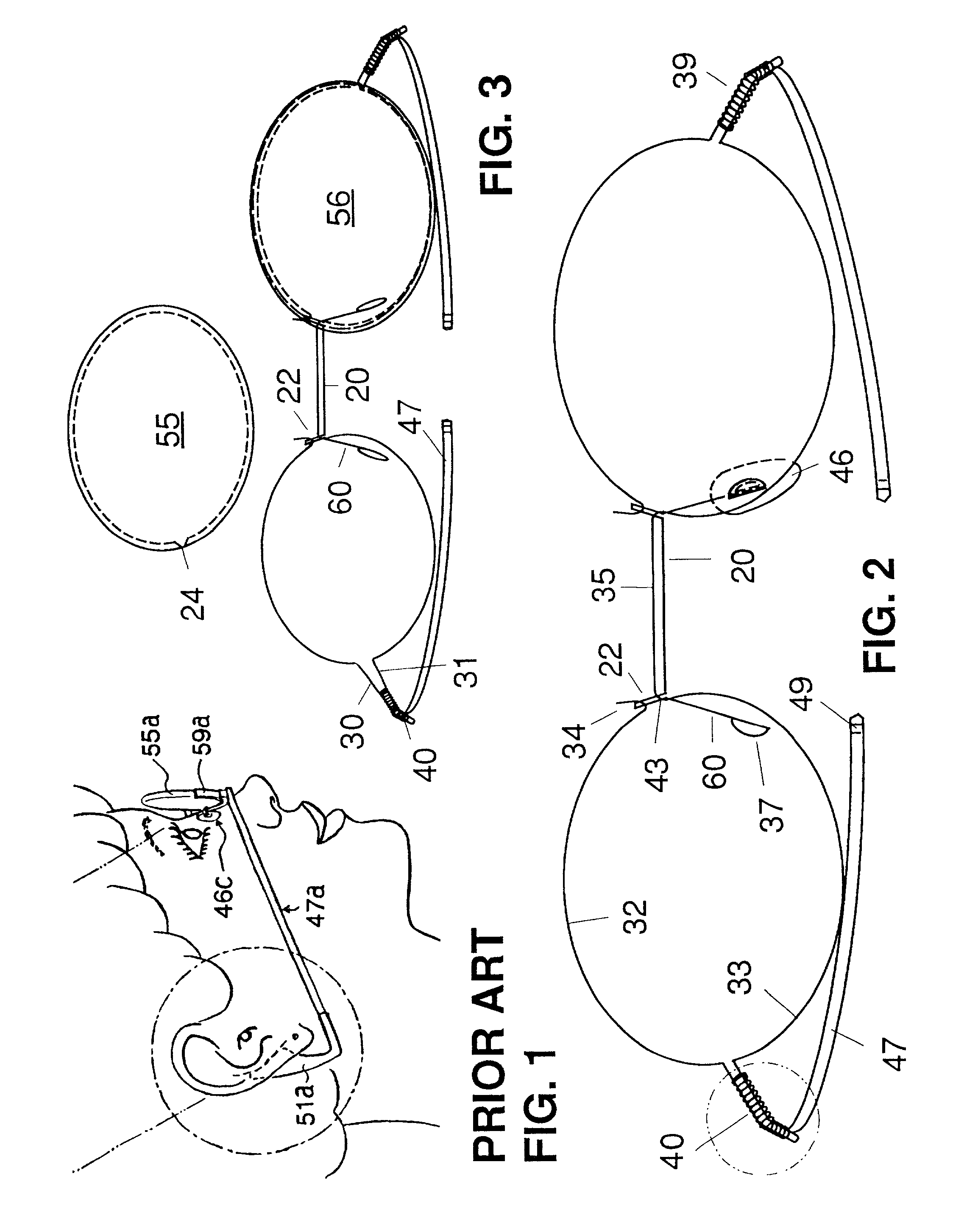
[0070] FIG. 1 is Prior Art shown in U.S. Pat. No. 5,859,684, FIG. 14, where the embodiment of that system is shown on a wearer; RHS (right-hand side) view. Notations are ear-rest 51a, sidepiece 47a, nosepad 46c, RHS lense 55a, and frame 59a. These part names are used in this text.

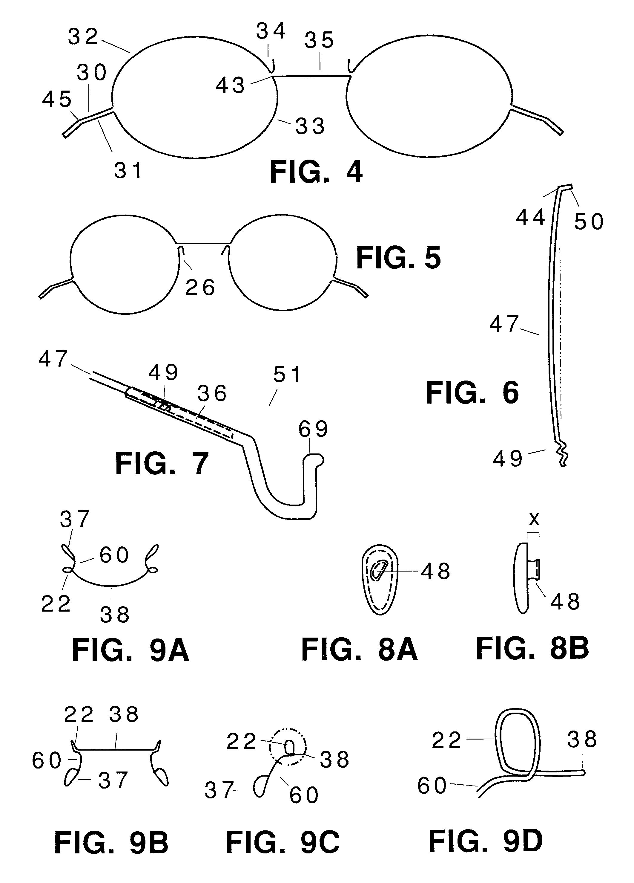
[0071] FIG. 2 shows an eyewear assembly of the invention's parts, front view. In this embodiment, upper portion RHS frame eyewire 32 terminates medially in frame hook 34. The medial end of lower portion RHS frame eyewire 33 becomes frame bridge 35 at frame bow 43 (43 is shown better in FIG. 4.) Hook 34 and bow 43 are semi-encircled by nosebridge hook 22. Nosebridge bridgeportion 20 positions under frame bridge 35 (but can continue frontwardly / upwardly around frame bridge). A lateral edge of bridgeportion 20 ovals upwardly to rearwardly to downwardly as hook 22. After hook 22, the nosebridge continues rearwardly / downwardly as nosebridge nosepad arm 60. Also angling arms laterally can help slant nosepads, whe...


PUM


Abstract

This invention is a completely mechanical method of constructing eyewear, without brazing. An eyewear frame is formed by a continuous, bent, spring wire. Sidepiece 47 is fixedly attached to frame endpiece parts 30 and 31 by mating a bent portion of each within compression spring 40. The Vertically tall, transversely thin sidepieces can support with scant lateral pressure to a wearer's head, and can close can close against the frame without hinges. The length of a spring over the endpiece confines lense 56 in upper and lower portions of a frame's eyewire. Lense 55 has been removed by laterally compressing spring 40 around the folded-over endpiece parts and letting the ends of the endpiece parts spread vertically apart. Elongated members, unrelated to eyewear endpieces and sidepieces, can be fixedly attached and removed, and / or spread in the ways described above. A nosebridge can be formed by a continuous, bent, spring wire. It's transversely elongated bridgeportion 20 adds strength and stability to the frame. Hook 22 at an upper lateral end of the bridgeportion plus a bridgeportion frontward bow substantially mechanically encircle the frame's bridge in the latitudinal / longitudinal plane. The hooks and bow hold together upper and lower medial portions of a frame's eyewire. The vertical stability of the lenses, supported in the frame's eyewires, keeps the nosebridge from rotating. Nosebridge hook 22 continues downwardly / rearwardly as nosepad arm 60. The lateral angling of the arms also keeps the nosebridge from rotating. Each wire end of the arms upwardly loop; each loop can secure a nosepad balljoint.

Description

[0001] Parent Appn. Ser. No. 09 / 532,484 WIRE-FRAME EYEWEAR ASSEMBLY . . .[0002] Not ApplicableREFERENCE TO A MICROFICHE APPENDIX[0003] Not ApplicableBACKGROUND OF INVENTION[0004] This invention relates to spectacles, eyeglasses, and metal working means to assemble or disassemble using a circular spring applier or remover. More specifically, a means to secure lenses, temples / sidepieces, earpieces, and nosepieces together as completed eyewear, and a means to fixedly attach mated elongated members with a compression spring.[0005] Up till now, metal eyewear frames have been constructed by brazing / soldering and require great precision to make them consistent and have matched sides. Prior-art metal frames often use screws to secure two brazed-on, tapped, mateable, barrel ends of a bezel tailored around a lense. Nosepad arms and a nosebridge are brazed to the bezels. Nosepad arms often have a brazed on clamp or centrally-tapped cup. The nosepads, secured with a screw to a cup, become immob...

Claims


Application Information

Patent Timeline
Patent Type & Authority Applications(United States)
IPC IPC(8): G02C1/04G02C1/06G02C5/00G02C5/06G02C5/14G02C5/16
CPCG02C1/04G02C1/06G02C3/003G02C5/001G02C5/008G02C5/06G02C5/143G02C5/16G02C2200/10
Inventor RITTMANN, JEAN V.
Owner RITTMANN JEAN V
Why Eureka
Try Eureka