System and method for decreasing tire pressure

a technology of tire pressure and system, which is applied in the field of system and a method for decreasing tire pressure, can solve the problems of limited rate at which the tire pressure can be decreased, the volume of current systems for decreasing the tire pressure of one or more wheel assemblies, and the wide operating pressure range, so as to reduce the pressure of the pressurized fluid in the chamber, the effect of tire pressur

Active Publication Date: 2016-06-16
DANA HEAVY VEHICLE SYSTEMS GROUP LLC
View PDF0 Cites 7 Cited by
  • Summary
  • Abstract
  • Description
  • Claims
  • Application Information

AI Technical Summary

Benefits of technology

[0005]A method for decreasing tire pressure is provided. In an embodiment, the method comprises providing a wheel assembly which defines a chamber that houses a pressurized fluid. A wheel valve assembly is provided in fluid communication with the chamber. The wheel valve assembly is operable between an open position and a closed position and comprises an area having a first flow capacity. A variable area valve assembly is provided and is selectively in fluid communication with the wheel valve assembly. The variable area valve assembly comprises an area formed in a perforation that has a second flow capacity. The second flow capacity is less than the first flow capacity. A target tire pressure is selected. If a pressure of the pressurized fluid in the chamber is greater than the target tire pressure, then the pressure of the pressurized fluid in the chamber is decreased by directing a flow of pressurized fluid from the wheel assembly through the wheel valve assembly and the variable area valve assembly.

Problems solved by technology

Current systems for decreasing the tire pressures of one or more wheel assemblies having a large volume and wide operating pressure range are limited by cost, complexity and the rate at which the tire pressures can be decreased.

Method used


Image

  • System and method for decreasing tire pressure
  • System and method for decreasing tire pressure
  • System and method for decreasing tire pressure

Examples


Embodiment Construction

[0024]It is to be understood that the invention may assume various alternative orientations and step sequences, except where expressly specified to the contrary. It is also to be understood that the specific systems, methods, assemblies and features illustrated in the attached drawings, and described in the following specification are simply exemplary embodiments of the inventive concepts. Hence, specific dimensions, directions, or other physical characteristics relating to the embodiments disclosed are not to be considered as limiting, unless expressly stated otherwise. Also, although they may not be, like elements in various embodiments may be commonly referred to with like reference numerals within this section of the application.

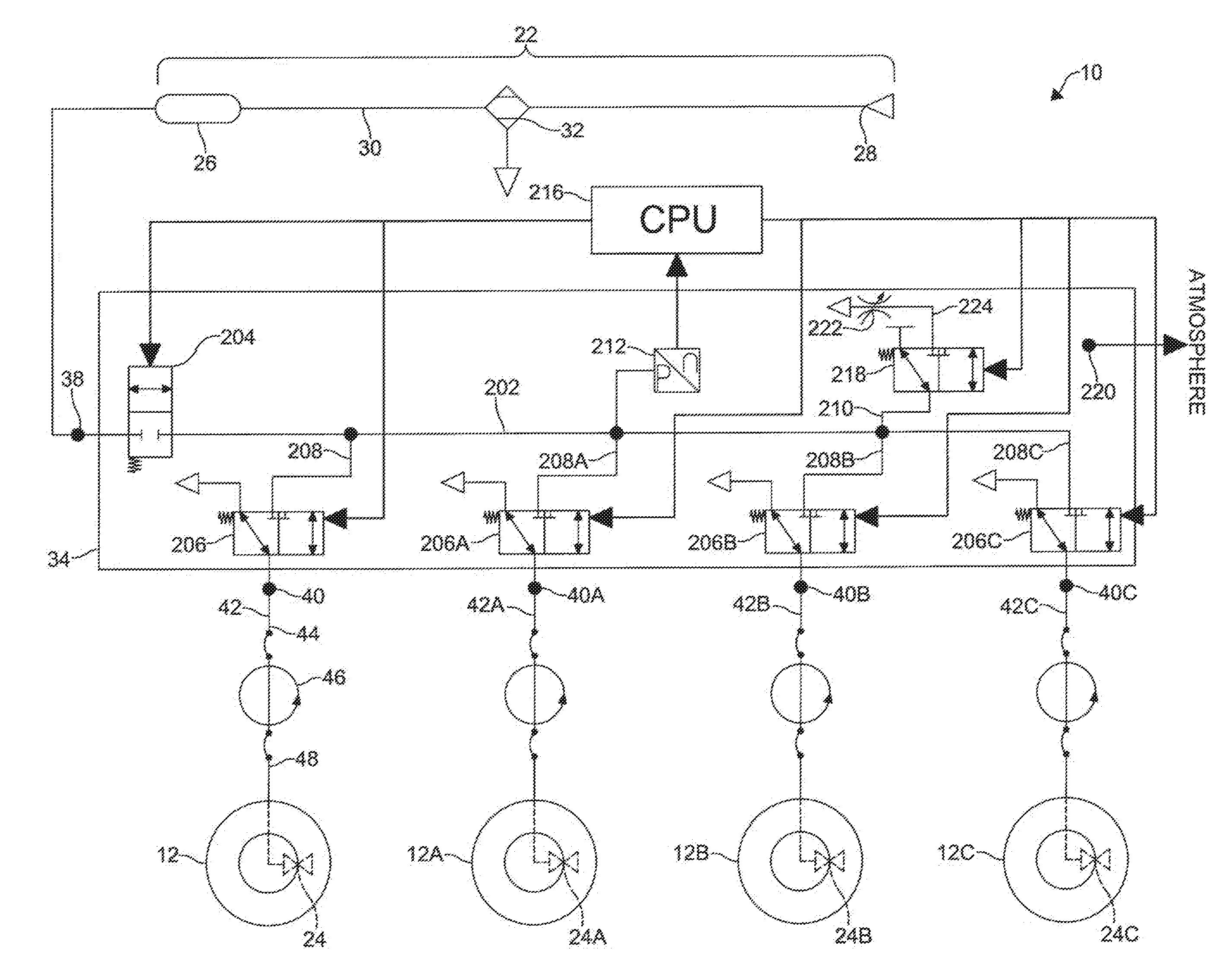
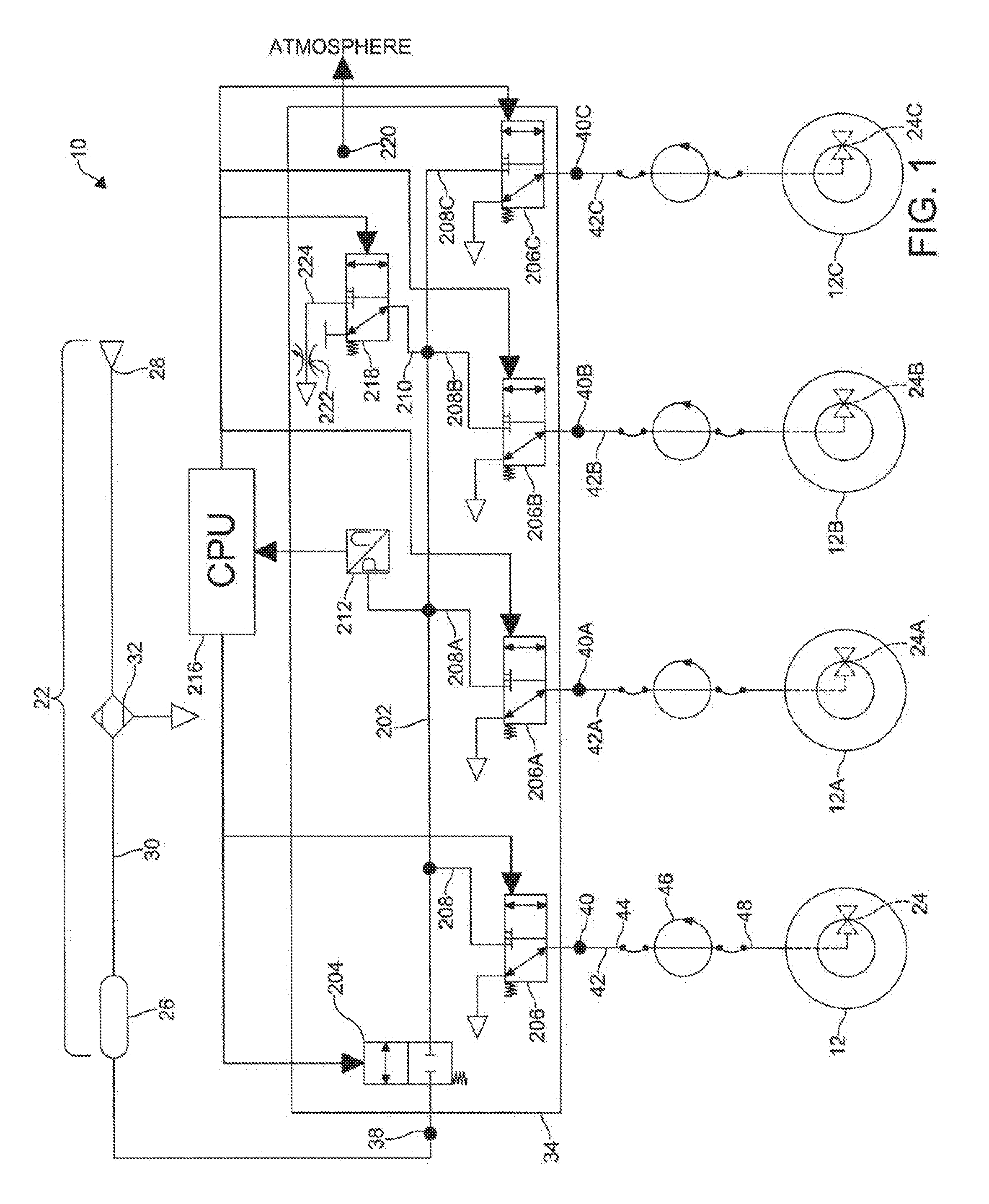
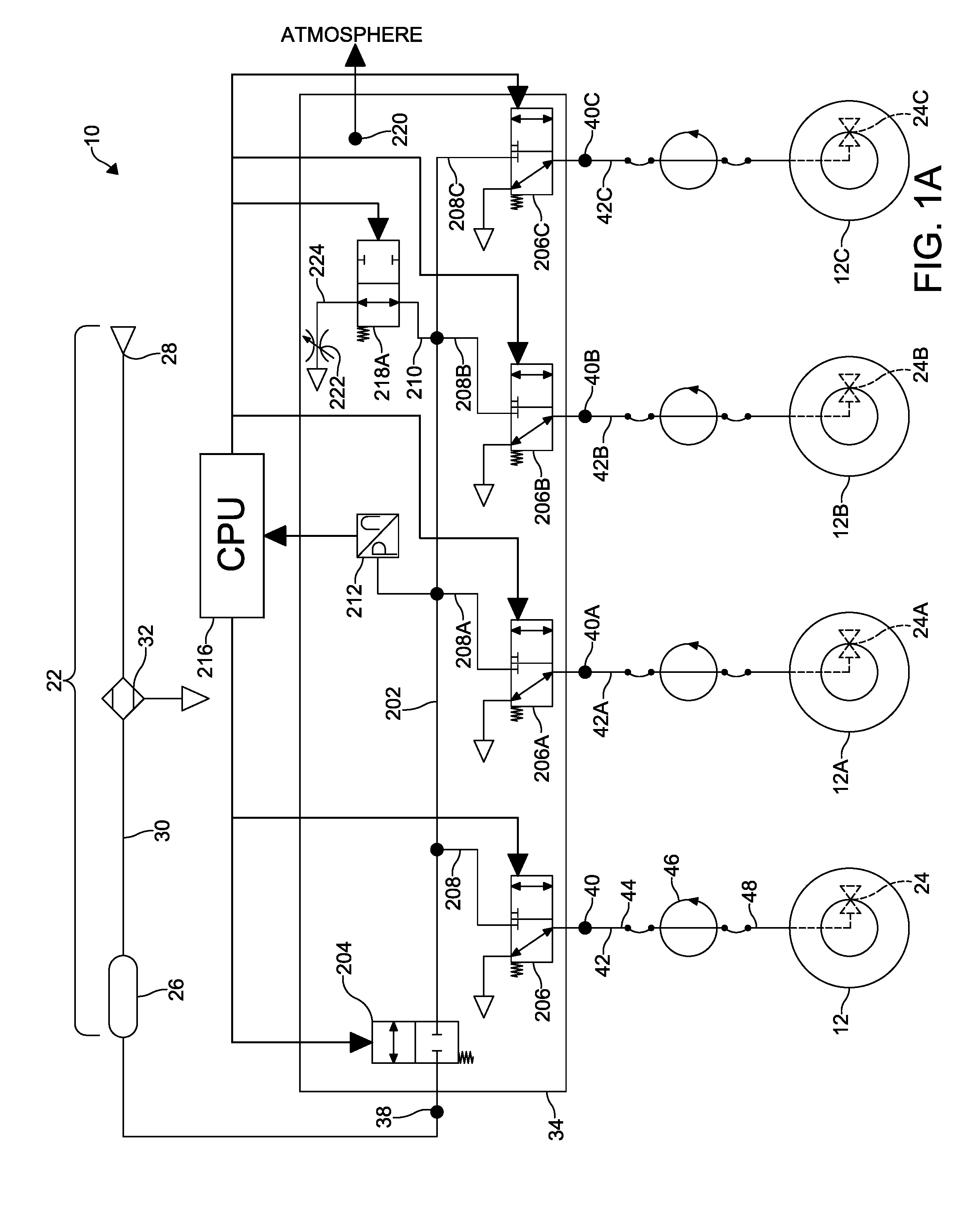
[0025]A system and a method for decreasing tire pressure are described herein. With reference to FIGS. 1-13, certain embodiments of the system 10 and the method will now be described.

[0026]The system and method described herein may be utilized with a veh...


PUM


Abstract

A method for decreasing tire pressure includes providing a wheel assembly which defines a chamber that houses a pressurized fluid. A wheel valve assembly is provided in fluid communication with the chamber. The wheel valve assembly is operable between an open position and a closed position and includes an area having a first flow capacity. A variable area valve assembly is provided and is selectively in fluid communication with the wheel valve assembly. The variable area valve assembly includes an area formed in a perforation that has a second flow capacity. The second flow capacity is less than the first flow capacity. A target tire pressure is selected. If a pressure of the pressurized fluid in the chamber is greater than the target tire pressure, then the pressure of the pressurized fluid in the chamber is decreased.

Description

CROSS-REFERENCE TO RELATED APPLICATIONS[0001]This application is a continuation-in-part of the non-provisional application granted Ser. No. 14 / 177,402 filed on Feb. 11, 2014, the entire disclosure of which is hereby incorporated by reference, which claims the benefit of the provisional applications granted Ser. Nos. 61 / 763,048 filed on Feb. 11, 2013, 61 / 776,431 filed on Mar. 11, 2013 and 61 / 925,749 filed on Jan. 10, 2014, the entire disclosures of which are hereby incorporated by reference.BACKGROUND OF THE INVENTION[0002]The invention relates to a system and a method for decreasing tire pressure.[0003]Certain types of vehicles such as, for example, tractors used for farming require that the tire pressure of their wheel assemblies be periodically adjusted for optimal performance. Generally, these types of vehicles have large volume wheel assemblies which operate over a wide range of tire pressures. Current systems for decreasing the tire pressures of one or more wheel assemblies hav...

Claims


Application Information

Patent Timeline
Patent Type & Authority Applications(United States)
IPC IPC(8): B60C23/00
CPCB60C23/00F16K15/063F16K15/20B60C23/00345B60C23/00363B60C23/00318B60C23/00354
Inventor MOZINGO, MELVIN B.RACINE, LLOYD G.SIDDERS, JASON M.KONA, VENKATA RAMAKANTHGILLEN, KURT P.KNAPKE, BRIAN V.
Owner DANA HEAVY VEHICLE SYSTEMS GROUP LLC
Why Eureka
Try Eureka