Tire cover assembly and tire structure for same

a technology for tire covers and components, applied in the direction of tyre tread bands/patterns, non-skid devices, vehicle components, etc., can solve the problems of shortened service life of tires, cumbersome replacement operation, and inability to avoid slippage. , to achieve the effect of convenient implementation of replacement operation and reduced tire air pressur

Inactive Publication Date: 2012-12-06
SON YOUNG IL
View PDF15 Cites 13 Cited by
  • Summary
  • Abstract
  • Description
  • Claims
  • Application Information

AI Technical Summary

Benefits of technology

[0022]According to the present invention, since the tire cover can be attached and detached to and from the cover support, replacement operation can be conveniently implemented when the tire cover is worn or damaged.
[0023]In the tire cover assembly according to the present invention, since the tire cover is supported by the cover support formed on the side surface of the tire, a problem can be prevented of the tire cover being impacted to a rim of tire wheel and then damaged due to centrifugal force resulting from high-speed rotation of the tire or decrease in air pressure of the tire.

Problems solved by technology

However, in the case of using the chains, there are shortcomings that the service life of tire is shortened due to load concentrated on contact portion between the chains and tire and since many areas of tire in which the chains are not positioned are kept in contact with road surface, occurrence of slip cannot be still avoided.
Meanwhile, in the case of the snow tire, there are shortcomings that replacement operation is very cumbersome and much time is required for the replacement operation and also effect of prevention of slip is insignificant.
However, this anti-slip cover has shortcomings that the fixing needles formed in inner surface of the cover body have to be installed so as to get stuck in the outer surface of tire and mounting and disassembling operations are not easy since annular cover body has to be spread outward to be fitted on the tire.
However, this tire cover is also mounted on the tire by spreading outward annular cover body to fit it on the tire, so has a problem that mounting and disassembling operations are not easy.

Method used


Image

  • Tire cover assembly and tire structure for same
  • Tire cover assembly and tire structure for same
  • Tire cover assembly and tire structure for same

Examples


Embodiment Construction

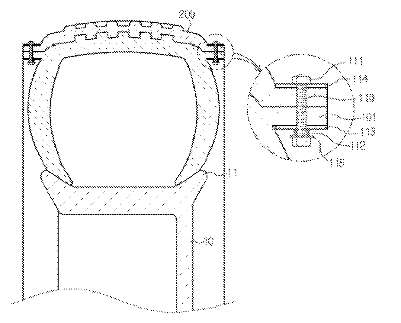
[0041]Hereinafter, preferred examples of the present invention will be described in detail with reference to the attached drawings. Prior to detailed description, it should be noted that terms or words used in the specification and claims should not be limitedly interpreted as normal or lexical meanings, but should be interpreted as meanings and concepts coinciding to technical concepts of the present invention based on the principle that inventors may properly define the concepts of the terms in order to explain their inventions in a best way. Therefore, examples described in the specification and constructions illustrated in the drawings are only the most preferred example of the present invention, and do not represent all of the technical concepts of the present invention, and thus it should be understood that various equivalents and modifications may be present which can replace them at the time of application of the present invention.

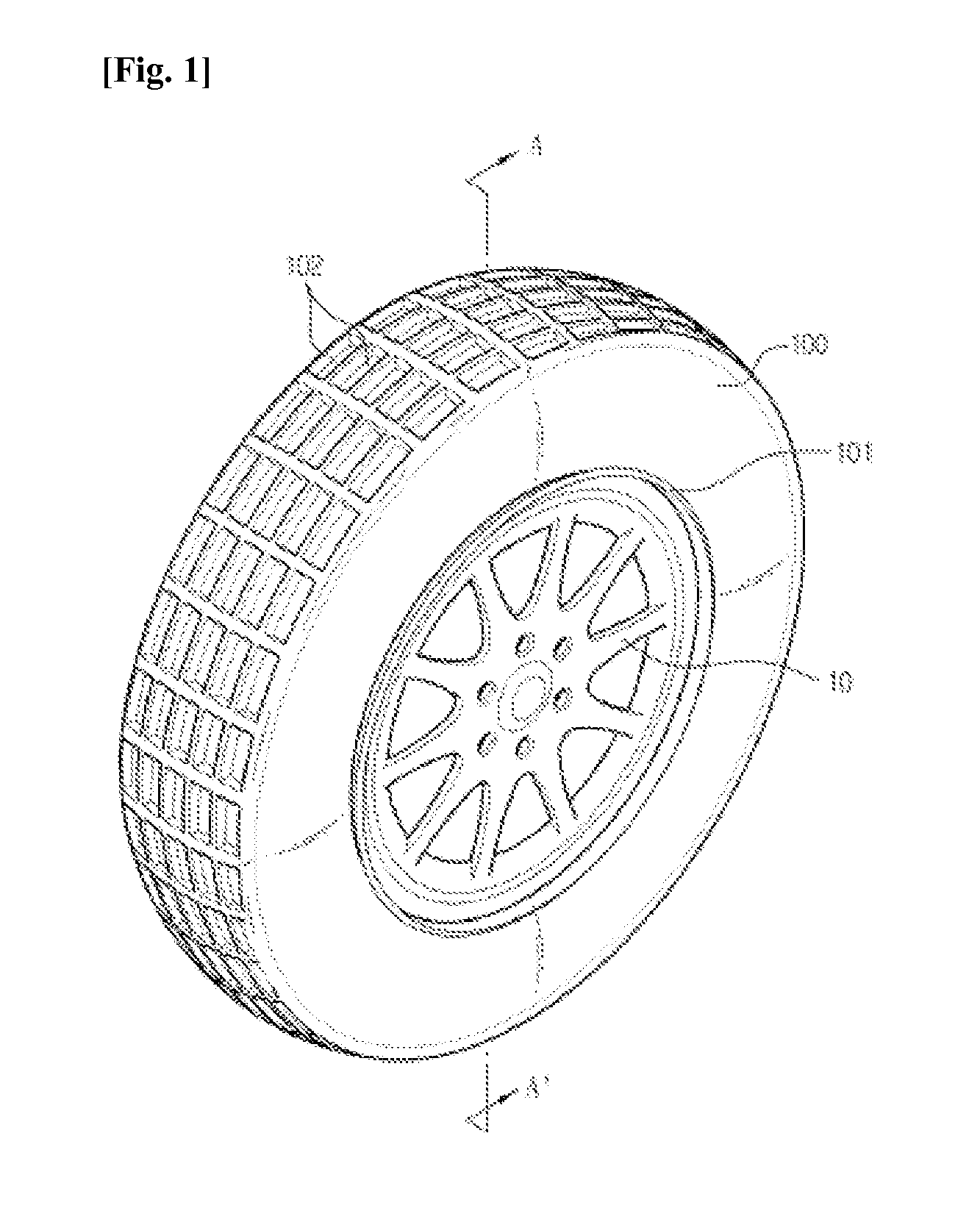
[0042]FIG. 1 is a perspective view illustrat...


PUM


Abstract

The present invention relates to a tire cover assembly comprising: a main tire body having a circular outer circumference; a tire cover configured to cover the main tire body; a cover support protruding from a side surface of the main tire body so as to support the tire cover in a radial direction of the main tire body, and disposed overall in a circular shape around a center of the main tire body; and a coupling medium configured to couple the tire cover to the cover support.

Description

CROSS-REFERENCE TO RELATED APPLICATION[0001]The present application claims a priority of Korean Patent Application No. 10-2010-0017190 filed on Feb. 25, 2010, and the disclosure of specification and drawings thereof is incorporated in the present application by reference in its entirety.FIELD OF THE INVENTION[0002]The present invention relates to a tire cover assembly used for driving of vehicle, more particularly, a tire cover assembly for vehicle providing a tire protecting cover detachably mounted on the outside of tire and a tire structure thereof.DESCRIPTION OF RELATED ART[0003]Commonly, for preventing slip of vehicle when it is driven on snow road or ice road, a method is widely used of previously fitting chains on the tire or mounting snow tire.[0004]However, in the case of using the chains, there are shortcomings that the service life of tire is shortened due to load concentrated on contact portion between the chains and tire and since many areas of tire in which the chains ...

Claims


Application Information

Patent Timeline
Patent Type & Authority Applications(United States)
IPC IPC(8): B60C27/20
CPCB60C27/066Y10T152/10279B60C27/20
Inventor SON, YOUNG-IL
Owner SON YOUNG IL
Why Eureka
Try Eureka