Tire pressure control system and components

a technology of tire pressure control system and components, which is applied in the direction of tire measurement, vehicle components, transportation and packaging, etc., can solve the problem of not being able to release the pressure medium from the tires, and achieve the effect of increasing the tire pressure, reducing the tire pressure, and increasing the tire pressur

Active Publication Date: 2021-11-23
KT PROJEKTENTWICKLUNGS GMBH +1
View PDF26 Cites 0 Cited by
  • Summary
  • Abstract
  • Description
  • Claims
  • Application Information

AI Technical Summary

Benefits of technology

[0010]The filling valve can be opened by increasing the pressure in the filling conduit to a pressure level that is sufficient to move the shut-off element of the filling valve from its closed position into an open position (this pressure, which depends on the tire pressure, is referred to hereinafter as “filling pressure”). In the open position, the pressurized pressure medium in the filling conduit can pass the filling valve and flow into the tire via the valve outlet. The tire is thus filled with pressure medium, correspondingly increasing the tire pressure. In other words, the filling valve is controlled by means of a pressure medium loading, which moves the filling valve from a closed position into an open position. The filling valve can also be referred to as an intake valve.
[0011]The emptying conduit, which is formed in the valve body and is separated from the filling conduit in a pressure-tight manner, can be used for reducing the tire pressure, i.e. for releasing pressure medium from the tire. When the tire valve is installed, pressure medium, similarly to what happens with the filling valve, can travel out of the tire via the valve outlet to the emptying valve so that the tire pressure is present on this side of the emptying valve and (optionally assisted by a spring force) pushes a shut-off element of the emptying valve into a closed position. If the emptying valve is in a closed position, no pressure medium can travel out of the tire into the emptying conduit. But if the emptying valve is in an open position, then pressure medium contained in the tire can pass through the emptying valve and travel into the emptying conduit and flow out through the emptying opening that is routed through the valve body. In this way, pressure medium is allowed to exit the tire, correspondingly reducing the tire pressure. The emptying valve can also be referred to as an outlet valve.

Problems solved by technology

Particularly with autonomous pressure medium supply systems, it is therefore not possible to release pressure medium from the tires while driving in order to perform a possibly needed reduction in tire pressure.

Method used


Image

  • Tire pressure control system and components
  • Tire pressure control system and components
  • Tire pressure control system and components

Examples


Embodiment Construction

[0049]In the following description of exemplary embodiments, elements that are the same or function in the same way have been provided with the same reference numerals.

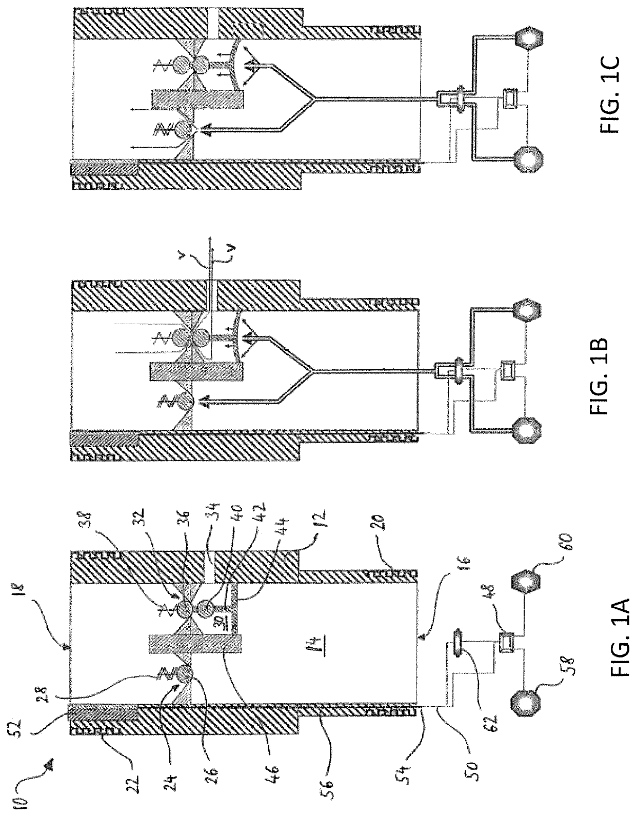
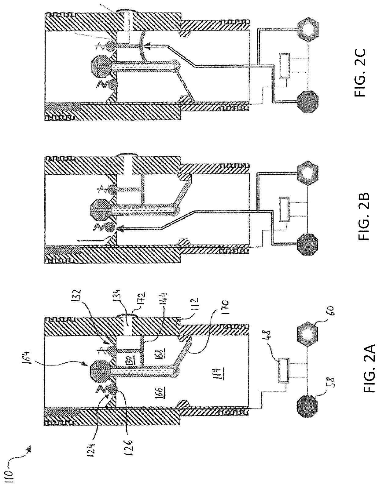
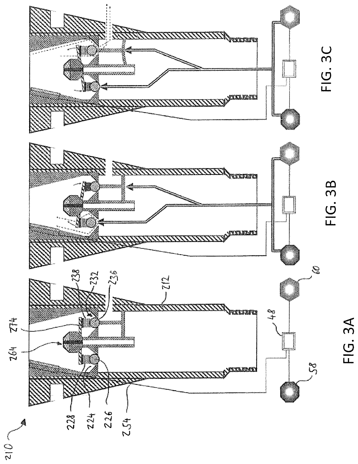
[0050]FIG. 1 shows a schematic sectional view of a tire valve 10 according to a first exemplary embodiment. In FIG. 1a, the tire valve 10 is shown in the normal state; in FIG. 1b, it is shown in a state during the emptying; and in FIG. 1c, it is shown in a state during the filling of a tire (not shown here). The tire valve 10 includes a valve body 12, in which a filling conduit 14 is routed from a valve inlet 16 to a valve outlet 18. The valve inlet 16 constitutes the part of the tire valve 10 via which the tire valve 10 communicates with a pressure medium line (not shown here) or is connected to it in a fluid-carrying manner. The valve outlet 18 constitutes the part of the tire valve 10 via which the tire valve 10 communicates with the inside of the tire or is connected to it in a fluid-carrying manner. In the region...


PUM


Abstract

A tire valve for controlled filling and emptying of a tire, having a valve body and a filling conduit, which is routed in the valve body from a valve inlet to a valve outlet and in which a filling valve is provided. In order to be able to perform an emptying of the tire, an emptying conduit, which is separated from the filling conduit in a pressure-tight manner, is formed in the valve body and includes an emptying valve, and from this emptying conduit an emptying opening leads through the valve body to the outside, wherein a shut-off element of the emptying valve is coupled to an element, which is movable by pressure medium loading, in such a way that a movement of the movable element, which is brought about by the pressure medium loading in the filling conduit, moves the shut-off element of the emptying valve into an open position.

Description

CROSS REFERENCE TO RELATED APPLICATION[0001]This application is a National Phase application of PCT International Patent Application PCT / US2016 / 068335, filed on 22 Dec. 2016.BACKGROUND OF THE INVENTIONField of the Invention[0002]The present invention generally relates to the field of adjusting the pressure in tires by means of tire valves and in particular, relates to a tire valve with which it is possible to carry out a controlled filling and emptying of a tire.SUMMARY OF THE INVENTION[0003]Tire valves are generally used to fill tires with a pressure medium such as compressed air. In vehicles such as passenger cars, trucks, or commercial vehicles, tire valves are usually positioned in the region of a rim on which the tire is mounted so that they are easily accessible from the outside. A pressure medium source external to the vehicle can be connected to the tire valve, for example by means of a hose line, in order to thus be able to check the tire pressure and correct it as needed.[...

Claims


Application Information

Patent Timeline
Patent Type & Authority Patents(United States)
IPC IPC(8): B60C29/06B60C29/00B60C23/00
CPCB60C29/068B60C29/005B60C23/003
Inventor SPINDLER, MARTIN P.TSIBERIDIS, KONSTANTINOS
Owner KT PROJEKTENTWICKLUNGS GMBH
Why Eureka
Try Eureka