
Control device, tire inflation system including said control device, and methods of operating said tire inflation system

a control device and tire inflation technology, applied in the direction of tire measurement, vehicle components, transportation and packaging, etc., can solve the problem that the conventional control device may not sufficiently limit the tire pressure, and achieve the effect of reducing the maintenance requirements, reducing the rolling resistance of the vehicle, and reducing the pressure of the vehicle tir

Pending Publication Date: 2022-06-23
DANA MOTION SYST ITAL SRL
View PDF0 Cites 0 Cited by
  • Summary
  • Abstract
  • Description
  • Claims
  • Application Information

AI Technical Summary

Benefits of technology

The present patent proposes a control device for a tire inflation system that includes an inlet for connection with a pressure source, a supply valve, at least one outlet for connection with a pneumatic tire, a supply valve, at least one channel valve, and at least one pressure-limiting valve. The control device is designed to limit tire pressure and improve control over tire inflation. The technical effect of the patent is to provide a more versatile control device for tire inflation systems that can limit tire pressure in a more efficient and effective manner.

Problems solved by technology

However, a conventional control device may not sufficiently limit tire pressure.

Method used


Image

  • Control device, tire inflation system including said control device, and methods of operating said tire inflation system

Examples


Embodiment Construction

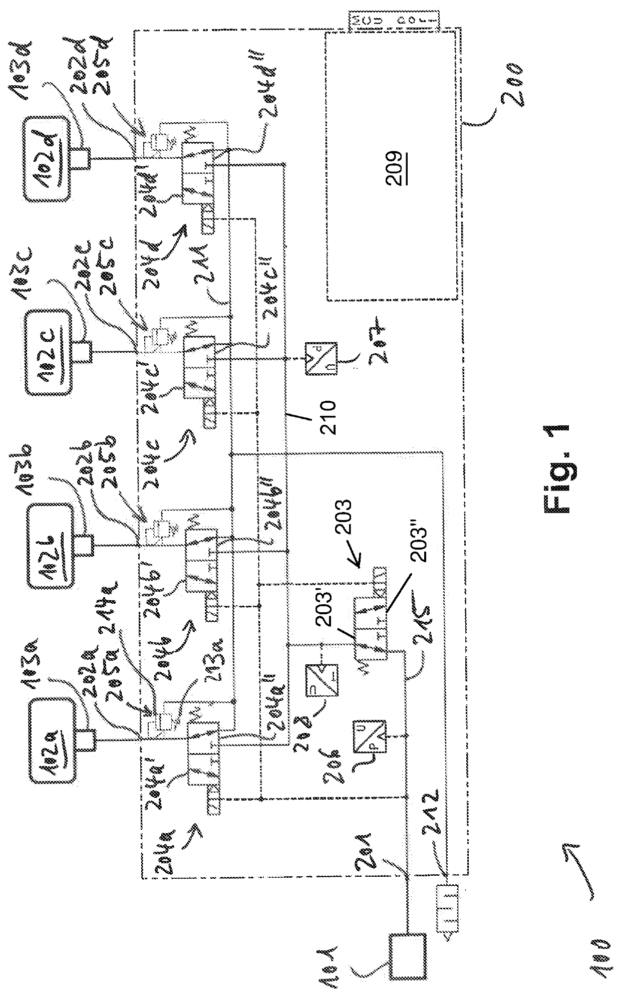
[0047]A schematic illustration of an embodiment of a tire inflation system 100 for a vehicle is provided in FIG. 1. The tire inflation system 100 comprises a pressure source 101, tires 102a-d, wheel valves 103a-d mounted on each tire, respectively, and a control device 200. The wheel valves 103a-d may be affixed to the tires 102a-d, respectively. Among other things, the control device 200 comprises an inlet 201 fluidly connected to the pressure source 101, outlets 202a-d selectively fluidly connected to the tires 102a-d via the wheel valves 103a-d, respectively, and a vent 212. The control device 200 is configured to selectively fluidly connect the pressure source 101 to one or more of the tires 102a-d, for example for inflating one or more of the tires 102a-d. The control device 200 is further configured to selectively place one or more of the tires 102a-d in fluid communication with the atmosphere or with a low pressure tank via the vent 212, for example for deflating one or more ...


PUM


Abstract

The present document relates to a control device for a central tire inflation system, comprising: an inlet for connection with a pressure source, at least a first outlet for connection with a first pneumatic tire, a supply valve, at least a first channel valve, and at least a first pressure-limiting valve, wherein the supply valve and the first channel valve selectively fluidly connect the inlet to the first outlet and are fluidly connected in series between the inlet and the first outlet, and wherein the first pressure-limiting valve a is fluidly connected to the first outlet for limiting a pressure at the first outlet. The present document further relates to a tire inflation system including said control device, and to methods of operating said control device.

Description

CROSS-REFERENCE TO RELATED APPLICATION[0001]The present application claim priority to German Patent Application No. 10 2020 216 212.3, entitled “CONTROL DEVICE, TIRE INFLATION SYSTEM INCLUDING SAID CONTROL DEVICE, AND METHODS OF OPERATING SAID TIRE INFLATION SYSTEM”, and filed on Dec. 17, 2020. The entire contents of the above-listed application is hereby incorporated by reference for all purposes.TECHNICAL FIELD[0002]The present disclosure relates to a control device, such as for use in a tire inflation system, to a tire inflation system including said control device, and to methods of operating said tire inflation system. Tire inflation systems of the presently proposed type may be installed on vehicles such as trucks or on working machines such as tractors, wheel loaders, dumpers, wheeled excavators, or the like.BACKGROUND AND SUMMARY[0003]Tire inflation systems are becoming crucial for certain vehicles such as trucks, tractors and earth-moving vehicles. Tire inflation systems ar...

Claims


Application Information

Patent Timeline
Patent Type & Authority Applications(United States)
IPC IPC(8): B60C23/00
CPCB60C23/00354B60C23/001B60C23/00309B60C23/10B60C23/00372
Inventor BENEVELLI, ALESSANDROBORRETTI, BIAGIOBUSCICCHIO, LUCATRINCHIERI, PIERGIORGIO
Owner DANA MOTION SYST ITAL SRL
Learn More