Image forming apparatus

a technology of forming apparatus and forming parts, which is applied in the direction of electrographic process apparatus, instruments, optics, etc., can solve the problems of not being able to remove the sealing member normally, taking a long time to start, and taking a long time to discriminate, so as to shorten the tim

Active Publication Date: 2016-06-16
CANON KK
View PDF4 Cites 0 Cited by
  • Summary
  • Abstract
  • Description
  • Claims
  • Application Information

AI Technical Summary

Benefits of technology

[0007]The present invention has accomplished in view of the above-described circumstances. A principal object of the present invention is to provide an image form...

Problems solved by technology

However, in such a developing device, there is a possibility that the sealing member is not removed normally during the initial driving.
However, in the case of the constitution disclosed in Japanese Patent No. 5183103, it takes much time until the developer flows from the second chamber into the first chamber and then is carried on the developing sleeve, and thus it takes much time from start of initial driving until whether or not the sealing member is removed is detected.
For this ...

Method used


Image

  • Image forming apparatus
  • Image forming apparatus
  • Image forming apparatus

Examples


first embodiment

[0028]First Embodiment of the present invention will be described using FIGS. 1 to 13. A general structure of an image forming apparatus in this embodiment will be described using FIG. 1.

Image Forming Apparatus

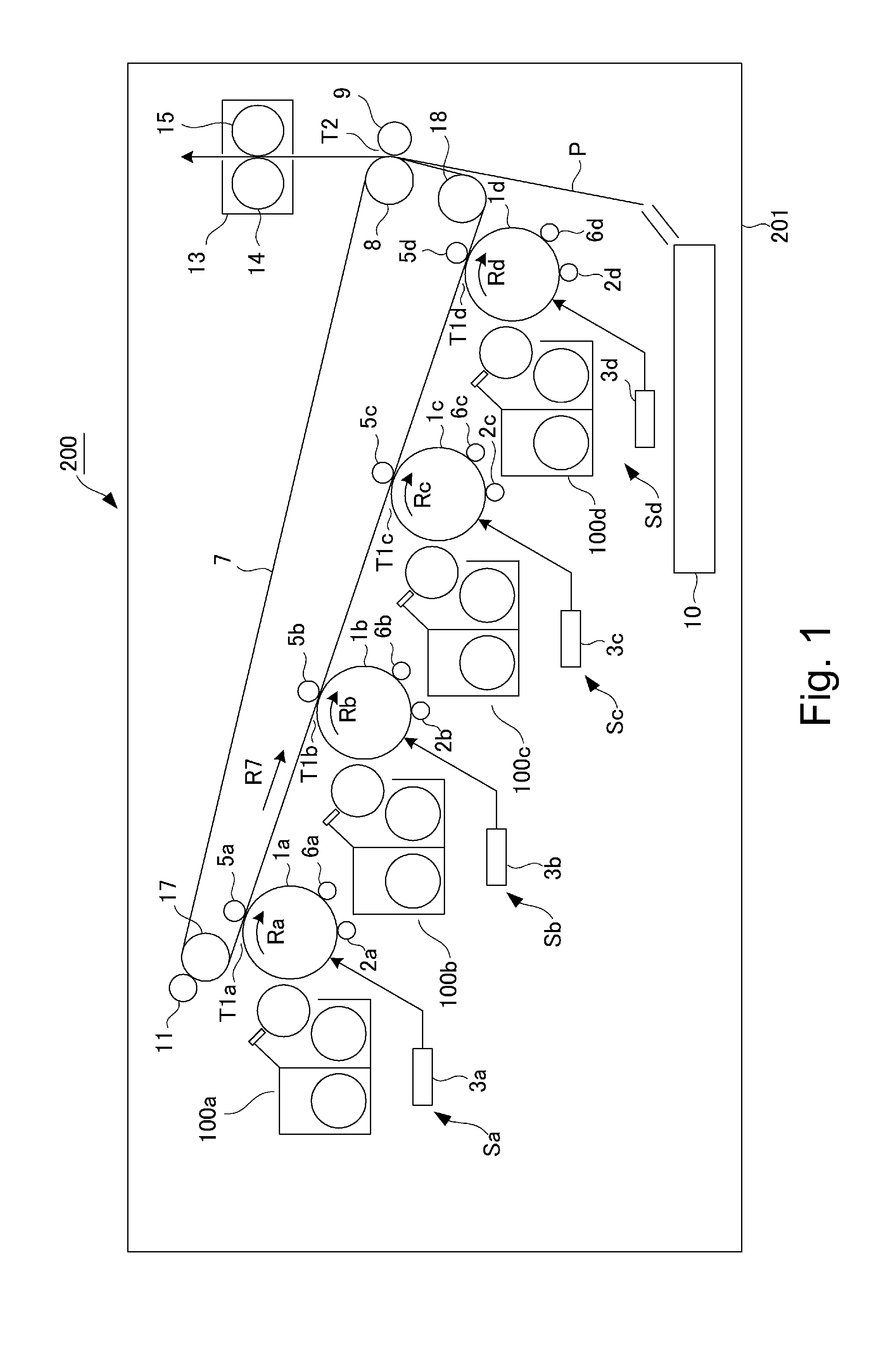
[0029]An image forming apparatus 200 is an example of a full-color image forming apparatus and includes four image forming portions (image forming stations) Sa, Sb, Sc, Sd provided along a rotational direction (arrow R7 direction) of an intermediary transfer belt 7 as an intermediary transfer member. The image forming portions Sa, Sb, Sc, Sd are image forming portions for forming toner images of yellow, magenta, cyan, black, respectively, and include photosensitive drums 1a, 1b, 1c, 1d, respectively, which are drum-shaped electrophotographic photosensitive members as image bearing members. In the following, the image forming portions for the respective colors have the same constitution and therefore the image forming portion Sa will be described as an representative, and other...

second embodiment

[0094]Second Embodiment of the present invention will be described using FIGS. 14 to 16. This embodiment is different from First Embodiment described above in that the stirring rib of the second stirring screw 111a is provided with a magnetic member. Accordingly, constitutions similar to those in First Embodiment are omitted or simplified from illustration or description and a portion different from First Embodiment will be principally described.

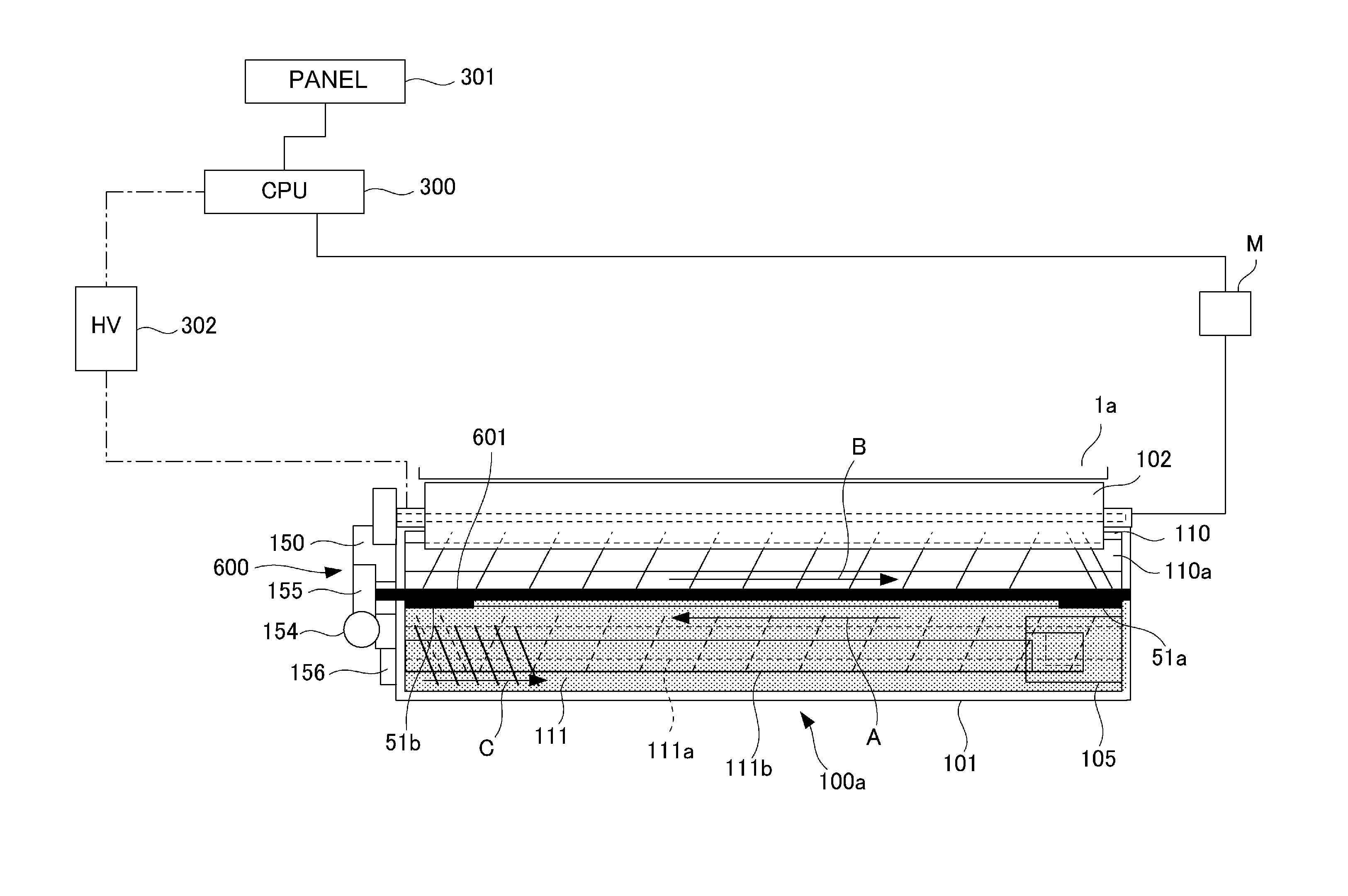
[0095]As shown in (a) of FIG. 14, of the plurality of the second stirring screw 111a in this embodiment, at least a stirring rib 1112a provided at a position opposing the inductance sensor 108 (FIG. 3) includes a magnetic member (material) 1113. The magnetic member is a ferrite of 50 mT in magnetic flux, for example. The stirring rib 1112a including the magnetic member 1113 may also be provided as all of the stirring ribs of the second stirring screw 111a or may also be provided only as the stirring rib opposing the inductance sensor 108. In...


PUM


Abstract

An image forming apparatus includes an image bearing member, a developing device, a driving device, and a controller. The developing device includes a developing container, a first feeding member, a second feeding member, a developer carrying member, a content sensor, and a sealing member. When information that the developing device is new is inputted, before an image forming operation is executed, the controller executes an initializing operation for driving the first feeding member and the second feeding member. The controller provides notification to the effect that the sealing member is not removed on the basis of an output of the content sensor during the initializing operation.

Description

FIELD OF THE INVENTION AND RELATED ART[0001]The present invention relates to an image forming apparatus such as a copying machine, a printer, a facsimile machine or a multi-function machine having a plurality of functions of these machines, and particularly relates to a constitution in which in an initial state of a developing device for forming a circulating path by a first chamber and a second chamber, a developer is sealed in the second chamber.[0002]In an image forming apparatus of an electrophotographic type or an electrostatic recording type, an electrostatic latent image is formed on a surface of an image bearing member such as a photosensitive drum, and the latent image is developed with a toner into a toner image. As a developing device for developing the latent image with the toner, a developing device using a two-component developer containing the toner and a carrier has been conventionally known. Such a developing device includes the first chamber and the second chamber,...

Claims


Application Information

Patent Timeline
IPC IPC(8): G03G15/08
CPCG03G15/0881G03G15/50G03G15/0856G03G15/0893G03G15/55
Inventor SAITO, FUMIYOSHIOKADA, NORIYUKI
Owner CANON KK
Why Eureka
Try Eureka