Method and System for Determining the Thermal Power Line Rating

a technology of thermal power lines and ratings, applied in the field of methods, can solve the problems of power line ratings being limited by the maximum conductor temperature, power lines in the field are always subject to movement and vibration, and the maximum allowable current rating or ampacity is primarily limited

Active Publication Date: 2016-06-23
AMPACIMON
View PDF7 Cites 10 Cited by
  • Summary
  • Abstract
  • Description
  • Claims
  • Application Information

AI Technical Summary

Problems solved by technology

Maximum allowable current rating or ampacity is primarily limited by the need to maintain at least a minimum safety clearance around the sagging suspended / anchored span of electrically conductive cable to prevent arcing.
Power line ratings could also be limited by maximum conductor temperature, due to material limitation(s), if reached before the maximum sag.
Indeed, power lines in the field are always subject to movements and vibrations, which may be very small but detectable by their accelerations in both time and frequency domains.
Besides the fact that these methods only allow a partial monitoring of the power line, such methods suffer from other drawbacks: optical techniques are sensitive to reductions of the visibility induced by meteorological conditions while the other measurement methods depend on uncertain models and / or data which may be unavailable and / or uncertain, e.g. wind speeds, topological data, actual conductor characteristics, etc.
It alleges the existence of a sensor about wind speed direction and amplitude but does not disclose how these sensors are constituted.

Method used


Image

  • Method and System for Determining the Thermal Power Line Rating
  • Method and System for Determining the Thermal Power Line Rating
  • Method and System for Determining the Thermal Power Line Rating

Examples


Embodiment Construction

[0051]As to the following defined terms, these definitions shall be applied, unless a different definition is given in the claims or elsewhere in this specification.

[0052]All numeric values are herein assumed to be preceded by the term “about”, whether or not explicitly indicated. The term “about” generally refers to a range of numbers that one of skill in the art would consider equivalent to the recited value (i.e. having the same function or result). In many instances, the term “about” may be indicative as including numbers that are rounded to the nearest significant number.

[0053]Although some suitable dimension ranges and / or values pertaining to various components, features and / or specifications are disclosed, one of skill in the art, incited by the present disclosure, would understand that desired dimensions, ranges and / or values may deviate from those expressly disclosed.

[0054]As used in this specification and in the appended claims, the singular forms “a”, “an”, and “the” incl...


PUM

PropertyMeasurementUnit
temperatureaaaaaaaaaa
widthaaaaaaaaaa

Abstract

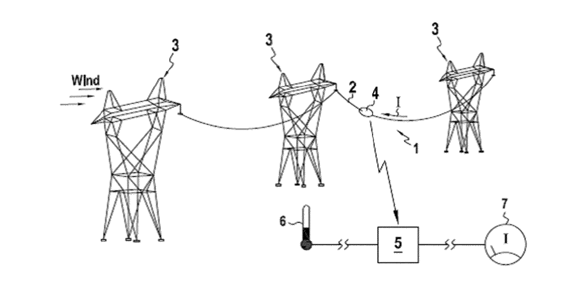
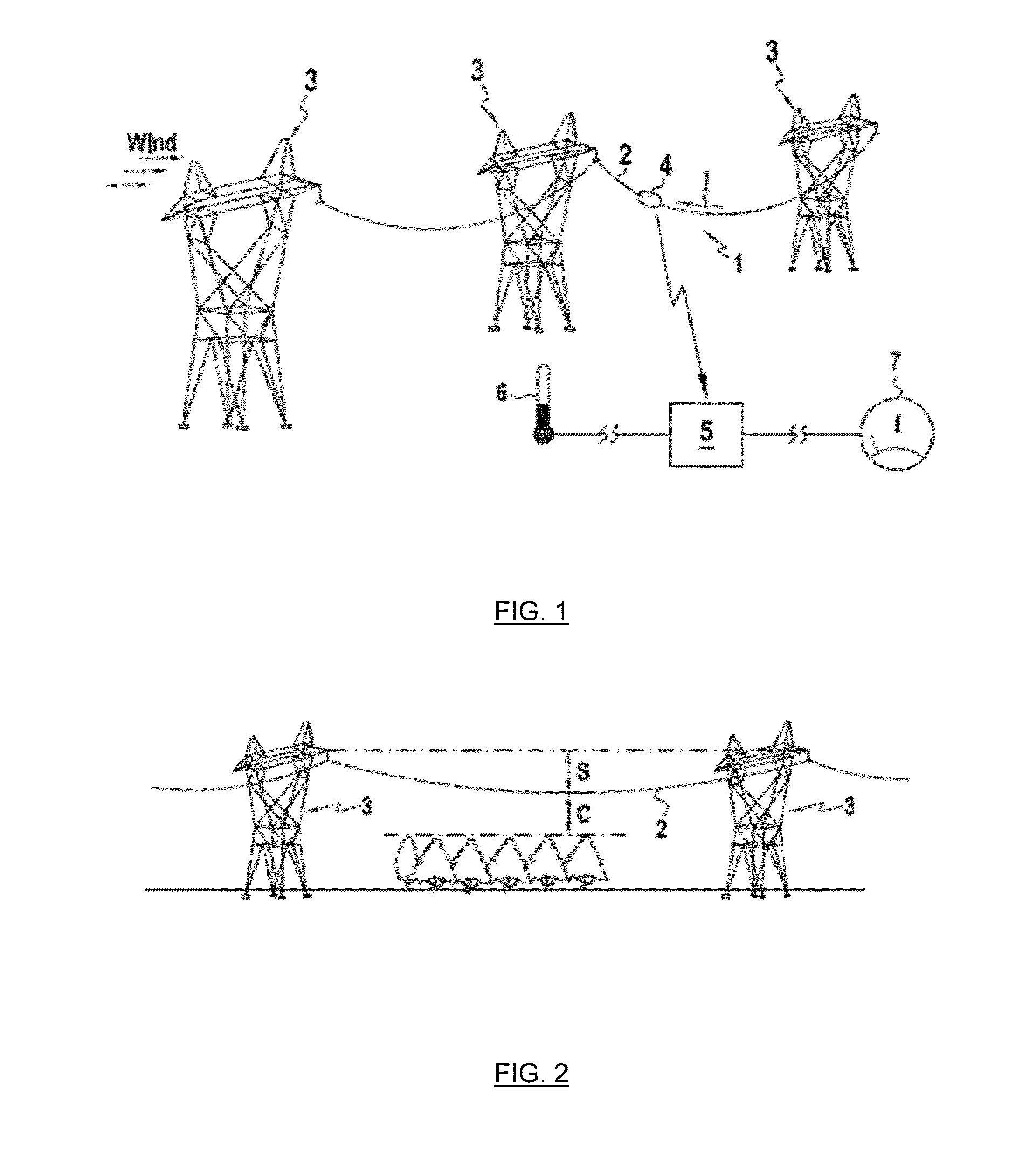
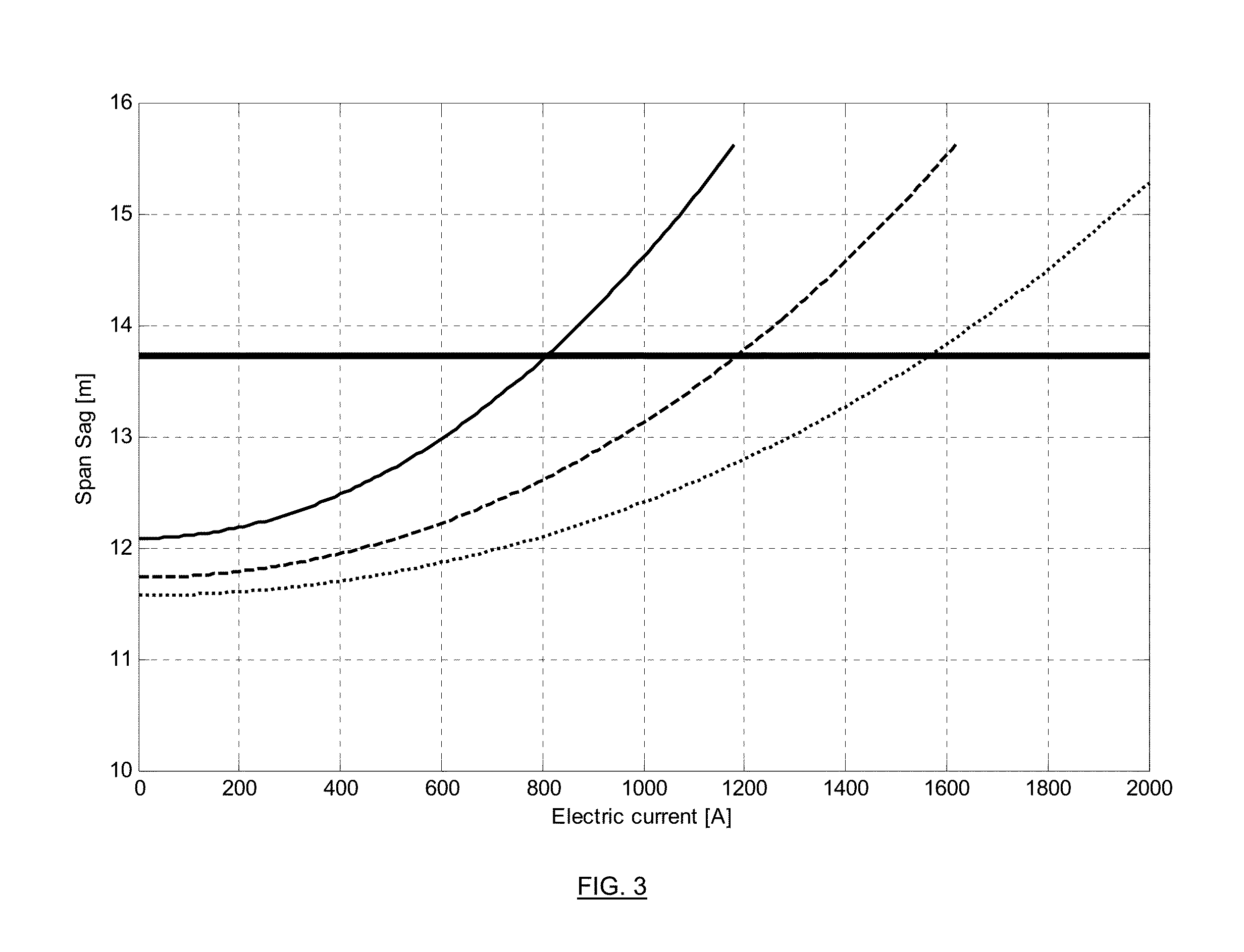
Method for measuring the power line thermal rating or maximum allowable current rating of an overhead power line with respect to a suspended / anchored cable span (2), comprising at least the following steps of:monitoring a motion of at least one point P of said suspended / anchored cable span (2) over a time interval;monitoring actual line current I, in A, over said time interval;determining an actual sag of said suspended / anchored cable, as a variable of actual line current;measuring or determining the effective wind speed of said suspended / anchored cable span (2) over said time interval;determining a sag reserve DF, in m, for thermal rating, which is the distance between the actual sag and a maximum allowable sag;determining the rate of change, tan(α), in m / A2, of the actual sag versus the square of the line current for the effective wind speed; anddetermining the power line thermal rating of the overhead power line, or ampacity, linked to a corresponding safety clearance, at measured or determined effective wind speed, by adding the square of actual current I to the ratio of the sag reserve DF by the sag rate of change, tan(α), at the effective wind speed, and taking the square root of that addition, i.e.Ampacity=I2+DFtan(α),wherein ampacity is in amperes.

Description

TECHNICAL FIELD[0001]The present invention is related to a method and system for determining the thermal power line rating (real-time and forecasted) with respect to an overhead electrical power line.[0002]Maximum allowable current rating or ampacity is primarily limited by the need to maintain at least a minimum safety clearance around the sagging suspended / anchored span of electrically conductive cable to prevent arcing. Power line ratings could also be limited by maximum conductor temperature, due to material limitation(s), if reached before the maximum sag.BACKGROUND[0003]The maximum allowable constant electrical current rating having to meet the design, security and safety criteria, such as electrical clearance, of a particular power line on which an electrically conductive cable is used is known under the term “ampacity”, as described for instance in “Sag-tension calculation methods for overhead lines”, published in 2007 as CIGRE Technical Brochure No. 324 by Study Committee B...

Claims


Application Information

Patent Timeline
Patent Type & Authority Applications(United States)
IPC IPC(8): G01R31/02G01N25/00G01R19/00
CPCG01R31/021G01N25/00G01R19/0092H02G7/02H02J3/00H02J2203/20Y04S10/30G01C5/00H02J13/00002H02J13/00034G01R31/58Y02E60/00
Inventor LILIEN, JEAN-LOUISNGUYEN, HUU-MINHGODARD, BERTRAND
Owner AMPACIMON
Why Eureka
Try Eureka