Modular enclosure elements employing cams forming detent features with latches

a module and enclosure technology, applied in the field of enclosure systems, can solve the problems of becoming more difficult to identify the available volume within the enclosure to route the supply power, and achieve the effect of efficient securement and removal

Inactive Publication Date: 2016-06-23
IBM CORP
View PDF2 Cites 4 Cited by
  • Summary
  • Abstract
  • Description
  • Claims
  • Application Information

AI Technical Summary

Benefits of technology

[0005]Embodiments disclosed herein include modular enclosure elements employing cams forming detent features with latches. A modular element may include a chassis body supporting electronic components. The modular element is removable from or secured to an enclosure using a latch. The latch may engage the enclosure and may remain engaged with the enclosure by being secured by interfacing with a cam. By forming the cam with a predetermined shape, a detent feature may be established with the latch to secure the latch and maintain the modular element locked to the enclosure. The latch may be disengaged from the cam by applying a disengagement motion to the cam and allow the latch to move relative to the chassis body and disengage from the enclosure. In this manner, the modular element is efficiently secured and removed from the enclosure with minimum obstruction to airflow to the electronic components.
[0006]According to one embodiment of the present invention, a modular element is disclosed. The modular element is removable from an enclosure during an unlocked mode and secured in enclosure during a locked mode. The modular element includes a chassis body supporting electronic components. The modular element further includes at least one latch in pivoting communication with the chassis body and configured to engage the enclosure during the lock mode. The modular element also includes at least one cam in pivoting communication with the chassis body and each including a shape having a catch cam extending in one direction and a cam arm extending in another direction, the catch cam and the cam arm are configured together to form a detent feature with the at least one latch during the lock mode. The detent feature secures the at least one latch with respect to the chassis body. The at least one cam includes an actuating surface configured to receive a disengagement motion which moves the at least one cam relative to the at least one latch during the unlock mode and which mobilizes the at least one latch relative to the chassis body to facilitate the disengagement of the chassis body from the enclosure. In this manner, the modular element may efficiently be secured and removed from the enclosure to enable hot swapping of electronic components for maintenance or upgrades.
[0007]According to one embodiment of the present invention, a method for securing and removing a modular element within an enclosure is disclosed. The method includes disposing at least a portion of a chassis body of the modular element within the enclosure, the chassis body supporting electronic components. The chassis body supporting electronic components, wherein the modular element includes at least one cam and at least one latch and both are in pivoting communication with the chassis body. The method further including securing the chassis body within the enclosure by moving the latch with respect to the chassis body to engage the at last one latch with the enclosure. The method also includes securing the at least one latch with respect to the chassis body by applying an installation force to the at least one latch to engage a lip of the at least one latch with a cam catch of the at least one cam and to form a slidable communication between a cam arm of the at least one cam and the at least one latch. The cam catch extends from an axis of rotation of the at least one cam in one direction and the cam arm extends from the axis of rotation of the at least one cam in another direction. In this manner, the modular element may efficiently be secured and removed from the enclosure with a reduced spatial volume enabling additional electronic components to populate the enclosure.
[0008]According to one embodiment of the present invention, an electronic device is disclosed. The electronic device includes an enclosure. The electronic device also includes a modular element removable from the enclosure. The modular element includes a chassis body supporting electronic components. The modular element further includes a latch in pivoting communication with the chassis body and engaging the enclosure during a lock mode. The modular element also includes a cam in pivoting communication with the chassis body and including a shape forming a detent feature with the latch during a lock mode, wherein the detent feature prevents movement of the latch with respect to the chassis body. The cam includes an actuating surface configured to receive a disengagement motion which bends a cam catch and a cam arm of the cam further apart so as to disengage the cam catch of the cam from a lip of the latch during an unlock mode, and which mobilizes the latch relative to the chassis body to facilitate disengagement the chassis body from the enclosure. The cam catch extends from an axis of rotation of the at least one cam in one direction and the cam arm extends from the axis of rotation of the at least one cam in another direction. In this manner, a high flow of airflow can be supplied to the electronic components in the enclosure with the small volume occupied by the cam and latch.

Problems solved by technology

With the resultantly highly-populated enclosures it is becoming more challenging to identify available volume within enclosures to route supply power cables and cooling air for components.

Method used


Image

  • Modular enclosure elements employing cams forming detent features with latches
  • Modular enclosure elements employing cams forming detent features with latches
  • Modular enclosure elements employing cams forming detent features with latches

Examples


Embodiment Construction

[0019]Reference will now be made in detail to the embodiments, examples of which are illustrated in the accompanying drawings, in which some, but not all embodiments are shown. Indeed, the concepts may be embodied in many different forms and should not be construed as limiting herein. Whenever possible, like reference numbers will be used to refer to like components or parts.

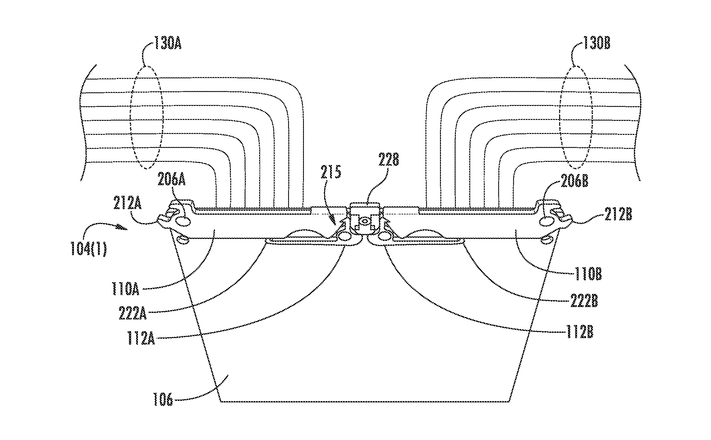
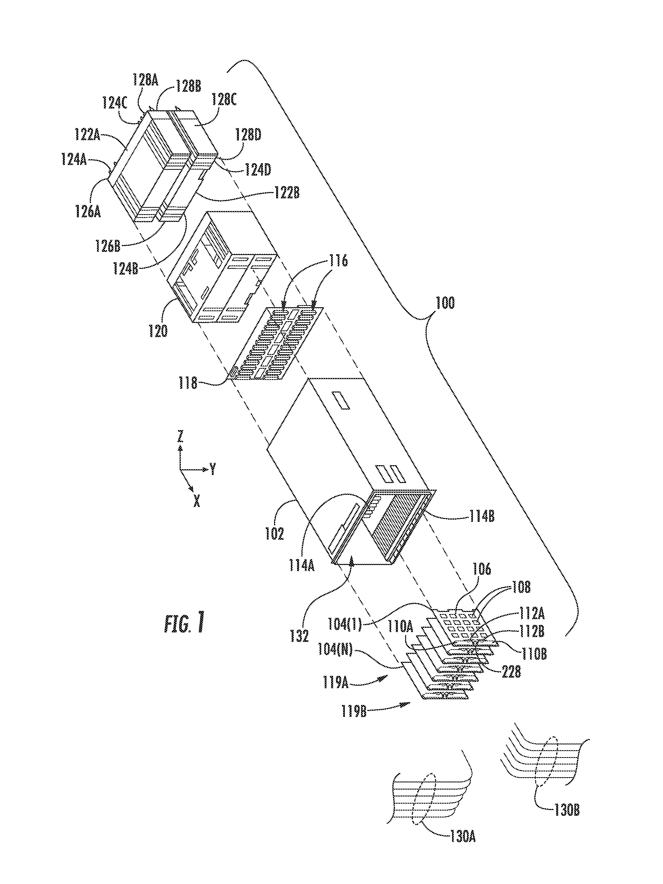
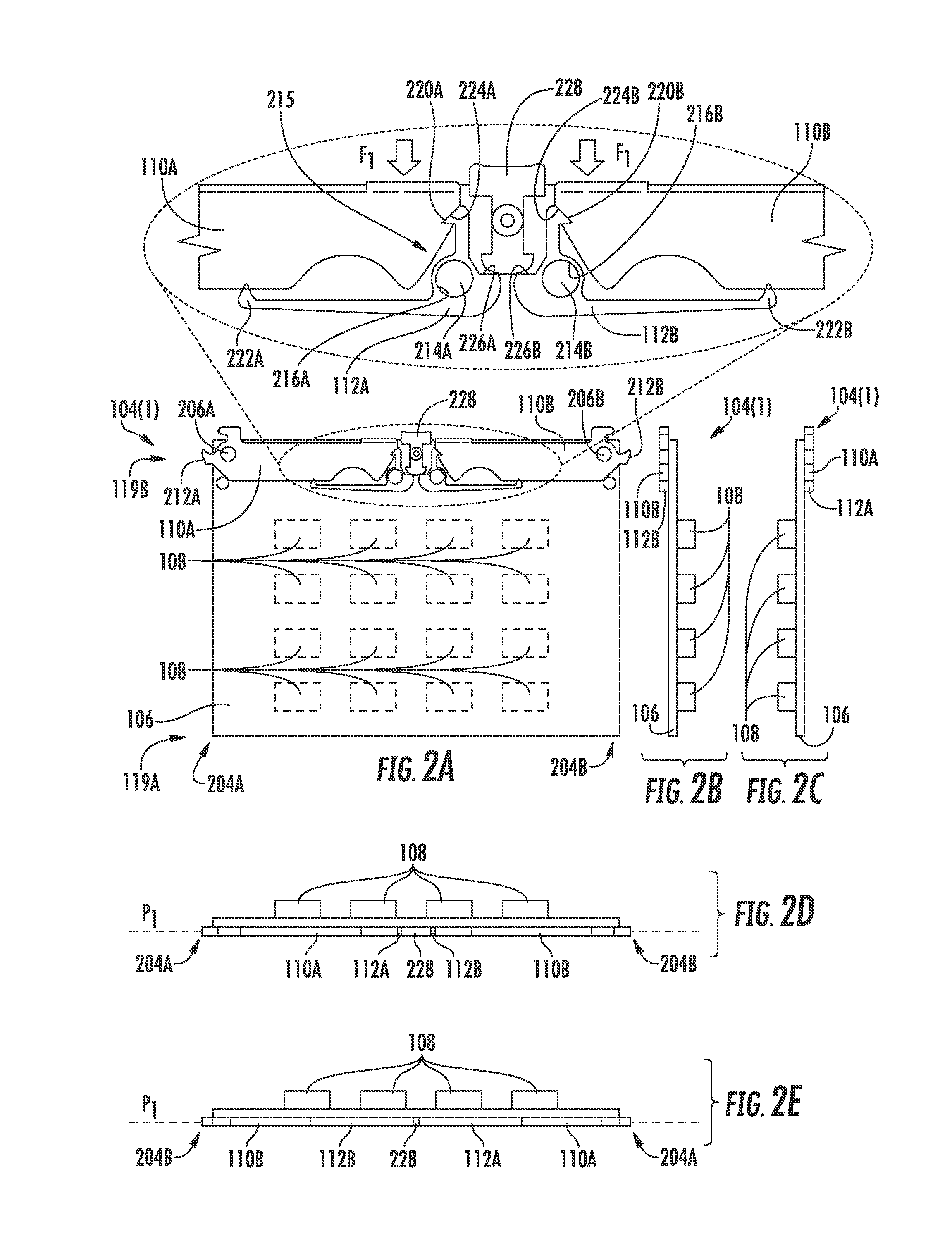
[0020]Embodiments disclosed herein include modular enclosure elements employing cams forming detent features with latches. A modular element may include a chassis body supporting electronic components. A modular element may include a chassis body supporting electronic components. The modular element is removable from or secured to an enclosure using a latch. The latch may engage the enclosure and may remain engaged with the enclosure by being secured by interfacing with a cam. By forming the cam with a predetermined shape, a detent feature may be established with the latch to secure the latch and maintain the mo...


PUM

PropertyMeasurementUnit
installation forceaaaaaaaaaa
axis of rotationaaaaaaaaaa
resilientaaaaaaaaaa

Abstract

Modular elements removable from enclosures and employing cams forming detent features with latches are disclosed. A modular element may include a chassis body supporting electronic components. The modular element is removable from or secured to an enclosure using a latch. The latch may engage the enclosure and may remain engaged with the enclosure by being secured by interfacing with a cam. By forming the cam with a predetermined shape, a detent feature may be established with the latch to secure the latch and maintain the modular element locked to the enclosure. The latch may be disengaged from the cam by applying a disengagement motion to the cam and allow the latch to move relative to the chassis body and disengage from the enclosure. In this manner, the modular element is efficiently secured and removed from the enclosure with minimum obstruction to airflow to the electronic components.

Description

CROSS-REFERENCE TO RELATED APPLICATIONS[0001]This application is a continuation of co-pending U.S. patent application Ser. No. 14 / 576,272, filed Dec. 19, 2014. The aforementioned related patent application is herein incorporated by reference in its entirety.BACKGROUND[0002]The present disclosure relates to enclosure systems having removable equipment elements, and in particular, to electronic components supported by elements which are removably disposed in enclosures.TECHNICAL BACKGROUND[0003]Benefits of enclosures include an establishment of an internal volume that provides protection and organization of the contents therein. In some applications, enclosures form a structural framework and protection of internal volumes, for example, from electromagnetic radiation, humidity, moisture, and heat. Items to be disposed within the internal volumes of enclosures may be supported as part of modular elements which are secured to the structural framework of the enclosure during use. The str...

Claims


Application Information

Patent Timeline
Patent Type & Authority Applications(United States)
IPC IPC(8): H05K5/02H05K7/14
CPCH05K7/14H05K5/0221H05K7/1409Y10T29/49815Y10T29/49822H05K7/18H05K5/0247H05K5/0213
Inventor BUTTERBAUGH, MATTHEW A.ECKBERG, ERIC A.SASSANO, CAMILLOSCHULTZ, KEVIN L.SHURSON, SCOTT A.
Owner IBM CORP
Why Eureka
Try Eureka