
Swath roller with controlled anchoring force

a technology of controlling anchoring force and controlling force, which is applied in the direction of mowers, agriculture tools and machines, and mowers, etc., can solve the problems of wind-driven movement of the swath

Active Publication Date: 2016-06-30
BOURGAULT INDS
View PDF0 Cites 0 Cited by
  • Summary
  • Abstract
  • Description
  • Claims
  • Application Information

AI Technical Summary

Benefits of technology

[0015]In a second embodiment the present disclosure provides a method of swathing a crop comprising moving a swather along the ground in an operating travel direction such that the swather cuts standing crop plants and lays the cut plants in a swath behind the swather supported on standing stubble of the cut crop plants; rotatably attaching a drum to a rear portion of the swather such that a rotational axis of the drum is oriented substantially horizontally and perpendicular to the operating travel direction; allowing the drum to move up and down and roll along a top of the swath such that the drum exerts a downward anchoring force on the swath and pushes the swath into the standing stubble; exerting a bias force on the drum and manipulating a bias force control to vary the bias force to vary the anchoring force in response to variations in the crop as the swather moves along the ground.
[0017]In prior art swath rollers where the drum floats up and down as it rolls along the top of the swath the anchoring force is the same regardless of the crop being cut. In a lighter crop, the swath may be pushed so far down into the standing stubble that the swath is difficult to pull up out of the stubble when the swath is harvested. Increased contact with the pick-up teeth of the harvester attempting to pick the swath out of the stubble can cause shelling of fragile crops and subsequent loss of seeds and lost revenue. Harvesting speed is reduced as well. Similarly in a heavier crop the anchoring force may be insufficient to push the swath sufficiently down into the stubble to anchor same and resist movement by the wind, again resulting in lost crop plants and revenue.

Problems solved by technology

In a lighter crop however, the swath can be much smaller and the standing stubble also much lower, so the swath may be pushed only slightly into the stubble or not at all, leaving the swath subject to movement from wind.

Method used


Image

  • Swath roller with controlled anchoring force
  • Swath roller with controlled anchoring force
  • Swath roller with controlled anchoring force

Examples


Embodiment Construction

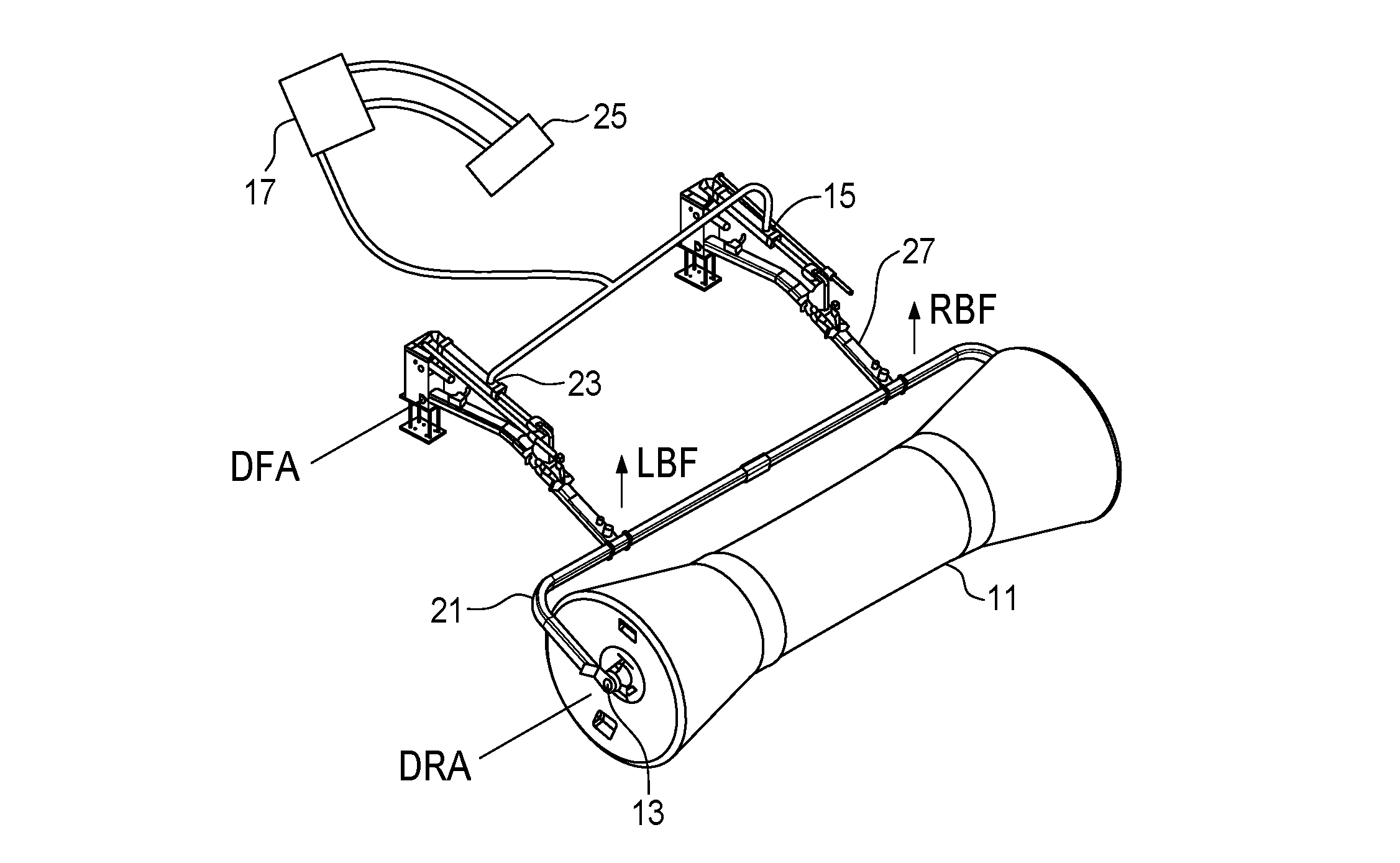
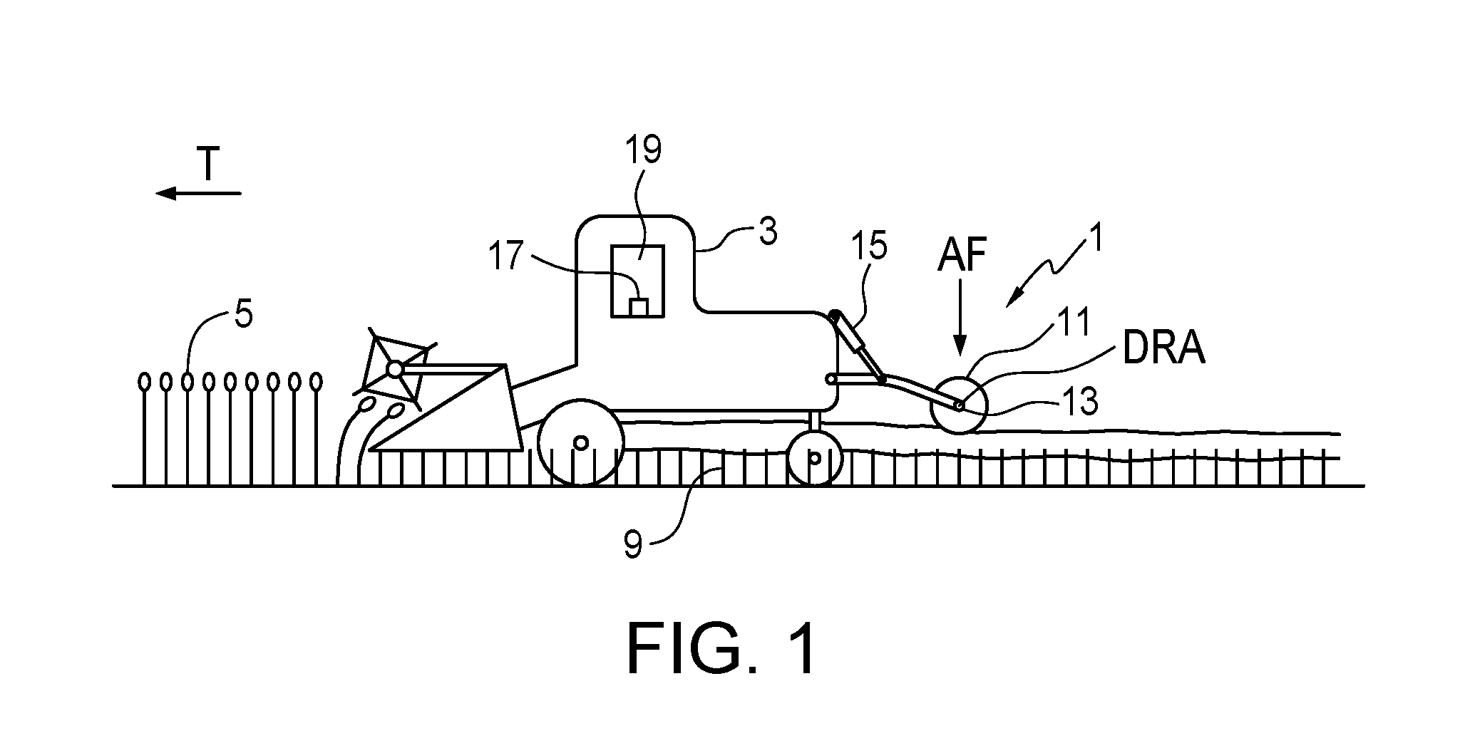
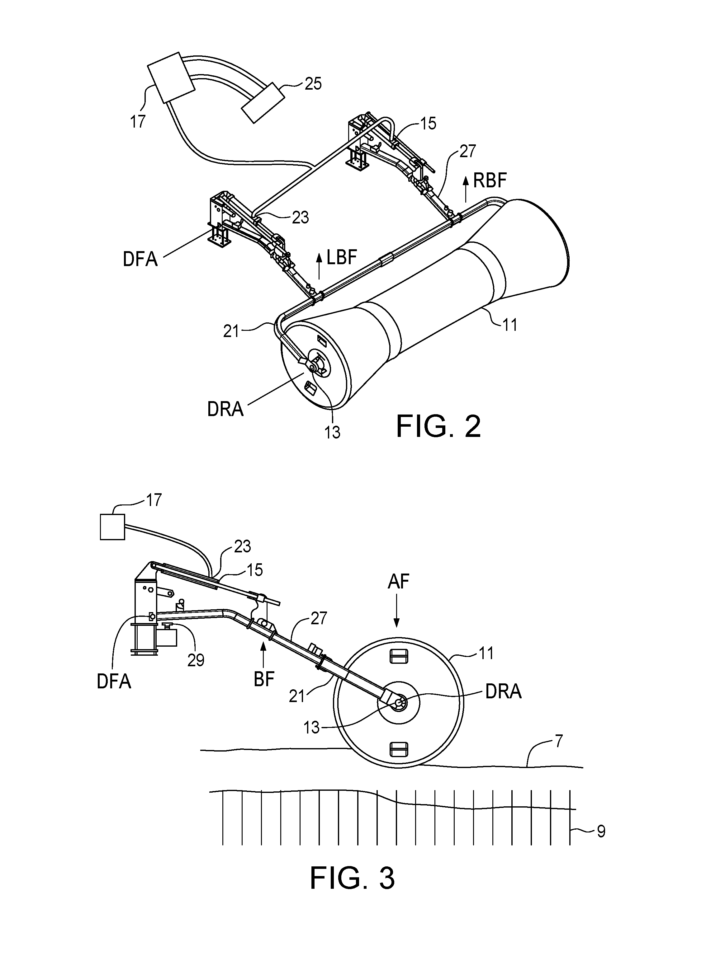
[0027]FIGS. 1-3 schematically illustrate an embodiment of a swath roller apparatus 1 of the present disclosure for use with a swather 3. The swather 3 is operative to cut standing crop plants 5 and lay cut plants in a swath 7 supported on standing stubble 9 of the cut crop plants as the swather moves along the ground in an operating travel direction T.

[0028]The apparatus 1 comprises a drum 11 rotatably attached to an axle 13. The axle 13 is adapted to be movably attached to a rear portion of the swather 3 such that the axle 13 is oriented substantially horizontally and perpendicular to the operating travel direction T, and such that the drum 11 moves up and down and rolls along a top of the swath 7 exerting a downward anchoring force AF on the swath 7 such as is known in the prior art where the drum 11 is allowed to float. The anchoring force AF is equal to the weight of the drum 11, axle 13, and any mounting framework for same. The rolling drum 11 pushes the swath 7 down into the s...


PUM


Abstract

A swath roller apparatus is adapted to be attached to a swather, where the swather is operative to cut standing crop plants and lay cut plants in a swath as the swather moves along the ground in an operating travel direction. A drum is rotatably attached to an axle that is adapted to be movably attached to a rear portion of the swather such that the axle is oriented substantially horizontally and perpendicular to the operating travel direction, and such that the drum moves up and down and rolls along a top of the swath exerting a downward anchoring force on the swath. A bias element is operative to exert a bias force on the axle, and a bias force control is operative to vary the bias force to vary the anchoring force.

Description

[0001]This disclosure is in the field of agricultural implements and in particular swath rollers for pushing crop swaths down into standing stubble.BACKGROUND[0002]In some agricultural areas it is popular to cut and windrow, or swath, crops before harvesting in order to promote earlier and more uniform maturing and to achieve the necessary drying of the crop. An implement known as a swather comprises generally a cutting header and belts to lay cut crop in a swath. The header is typically raised and lowered by lift hydraulic cylinders to follow ground contours and variations in crop height. Such swathers can be self-propelled, or towed behind a tractor.[0003]There is risk of loss or damage to a crop while it is in the swath. In the case of light and fragile crops such as canola, peas, flax or beans this risk includes loss of crop that is shelled out onto the ground due to wind action on the swath and the possibility of the wind actually dislocating and scattering the swath, making ef...

Claims


Application Information

Patent Timeline
Patent Type & Authority Applications(United States)
IPC IPC(8): A01D91/04
CPCA01D91/04A01D43/04A01D57/30
Inventor MILLER, GERRY LEE
Owner BOURGAULT INDS
Learn More