Orthopedic implants

Inactive Publication Date: 2016-06-30
GOTFRIED YECHIEL
View PDF2 Cites 13 Cited by
  • Summary
  • Abstract
  • Description
  • Claims
  • Application Information

AI Technical Summary

Benefits of technology

[0003]Applications of the present invention include methods for operating on a subject, in order to treat pathological conditions. For example, an orthopedic implant may be inserted into an osteotomy in a tibia of the subject, bone graft material being coupled to the implant. By implanting the implant in the osteotomy, the patella of the subject is rotated about the axis of insertion, and a distance of the patella from the anterior distal portion of the femur (i.e

Problems solved by technology

In some pathologies, the patella is too close to the trochlea of th

Method used


Image

  • Orthopedic implants
  • Orthopedic implants
  • Orthopedic implants

Examples


Example

DETAILED DESCRIPTION OF THE DRAWINGS

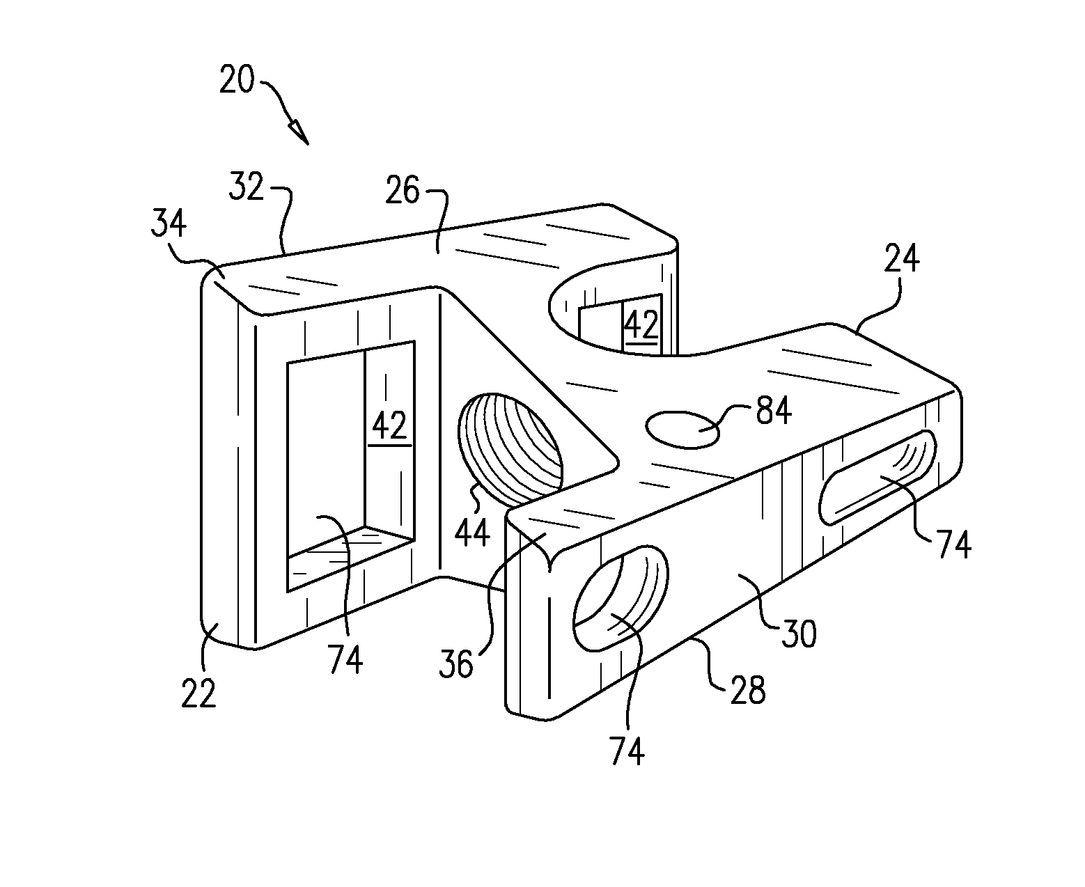
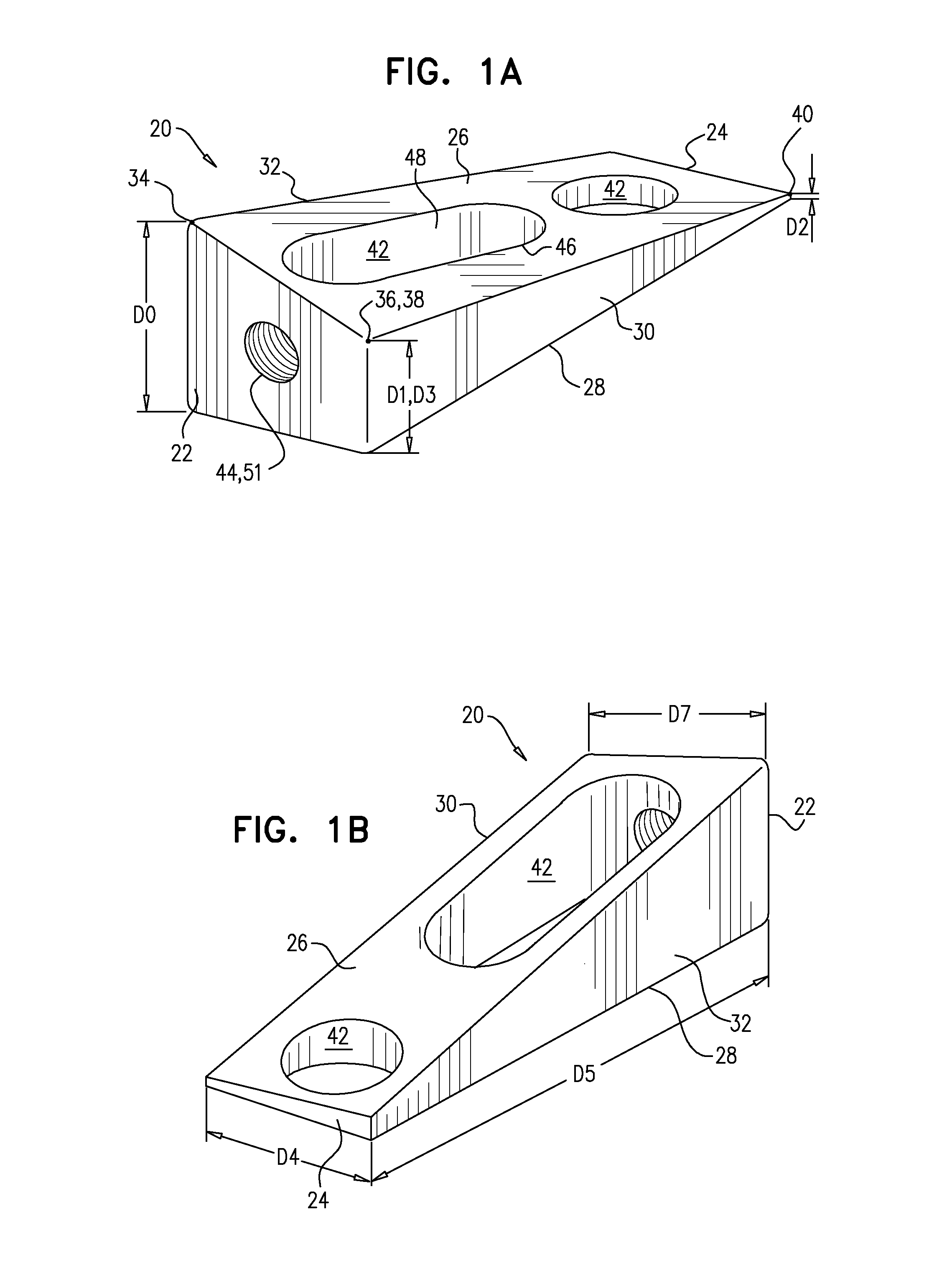
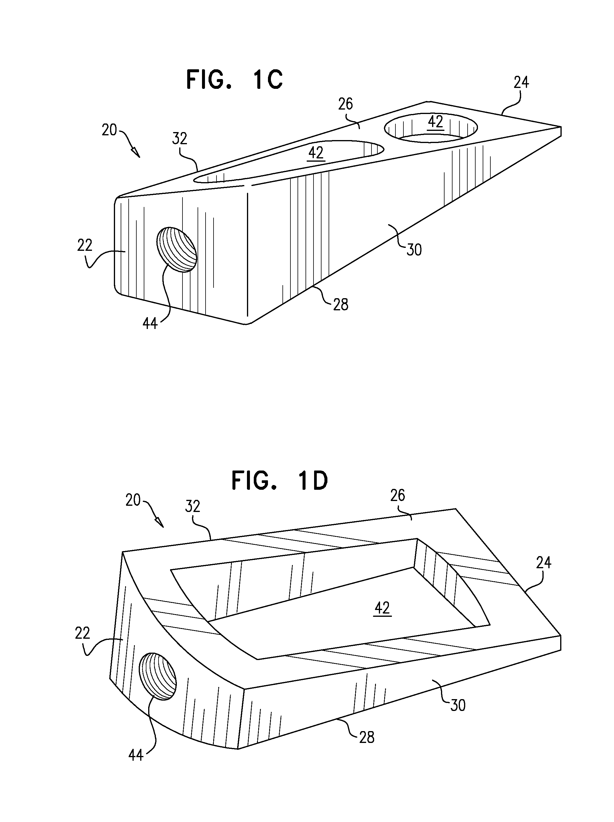
[0089]Reference is made to FIGS. 1A-4B, which are schematic illustrations of an orthopedic implant 20 for implanting in an anatomical site, in accordance with some applications of the present invention. Typically, the anatomical site is surrounded at least in part by one or more bones. For example, implant 20 may be implanted in a bone (e.g., an osteotomy, such as an osteotomy in a tibia), or a space between bones.

[0090]Implant 20 comprises a front end 22, a rear end 24, a top 26, a bottom 28, a right side 30, and a left side 32. As further described hereinbelow, e.g., with reference to FIG. 7, one function of implant 20 is to change an angular orientation of one bone portion (i.e., part or all of a bone) with respect to another bone portion. To facilitate this function, a distance D0 between top 26 and bottom 28 at one of the sides is greater than a distance D1 between the top and bottom at the other side, along at least a portion of the sides. (...


PUM


Abstract

Apparatus and methods are described, including an orthopedic implant for implanting in an anatomical site. The implant comprises a front end, a rear end, a top, a bottom, a right side, and a left side. A distance between the top and the bottom is (a) greater at a first location at one of the sides than at a second location opposite the first location at the other one of the sides, and (b) greater at a third location at the front end than at a fourth location opposite the third location at the rear end. The implant is shaped to define one or more passageways passing through the implant. Other applications are also described.

Description

FIELD OF THE INVENTION[0001]Applications of the present invention relate in general to orthopedic implants, and specifically, to orthopedic implants for changing an angular orientation of a bone.BACKGROUND[0002]In some pathologies, the patella is too close to the trochlea of the femur, and / or is improperly aligned with respect to the trochlea. In other pathologies, an intervertebral space in the spinal column is too small, and / or normal lordosis of the spinal column is absent. Multiple other pathologies relate to inappropriately aligned bones.SUMMARY OF THE INVENTION[0003]Applications of the present invention include methods for operating on a subject, in order to treat pathological conditions. For example, an orthopedic implant may be inserted into an osteotomy in a tibia of the subject, bone graft material being coupled to the implant. By implanting the implant in the osteotomy, the patella of the subject is rotated about the axis of insertion, and a distance of the patella from t...

Claims


Application Information

Patent Timeline
IPC IPC(8): A61F2/28A61F2/38
CPCA61F2/2846A61F2/3859A61F2002/2825A61F2002/2892A61F2/389A61B17/56A61B17/8095A61B2017/565A61F2/30734A61F2/4455A61F2002/30158A61F2002/30166A61F2002/30266A61F2002/30281A61F2002/30593A61F2002/30784A61F2002/3092A61F2002/4629A61F2310/00011A61F2310/00023A61F2310/00359A61F2/28A61F2/30767A61F2/4225A61F2/442A61F2/4603A61F2002/2835A61F2002/30736A61F2002/30774A61F2002/4233A61F2002/4627
Inventor GOTFRIED, YECHIEL
Owner GOTFRIED YECHIEL
Why Eureka
Try Eureka