Coupled and synchronous mirror elements in a lidar-based micro-mirror array

Active Publication Date: 2020-06-11
BEIJING VOYAGER TECH CO LTD
View PDF3 Cites 1 Cited by
  • Summary
  • Abstract
  • Description
  • Claims
  • Application Information

AI Technical Summary

Benefits of technology

[0020]Each of the plurality of mirror elements can be of the same size and dimensions, although other arrangements are possible. The first mirror element can be coupled to the support frame by at least one support hinge configured along the rotational axis and facilitates the rotation of the first and second mirror elements along the rotational axis. In some embodiments, the at least one support hinge, the support frame, the first and second mirror elements, and the coupling element can be a common, unitary structure formed on a common

Problems solved by technology

Despite the promise that LiDAR and other sensing systems bring to the continued development of fully autonomous transp

Method used


Image

  • Coupled and synchronous mirror elements in a lidar-based micro-mirror array
  • Coupled and synchronous mirror elements in a lidar-based micro-mirror array
  • Coupled and synchronous mirror elements in a lidar-based micro-mirror array

Examples


Example

[0032]Aspects of the present disclosure relate generally to object tracking systems, and more particularly to MEMS-based, synchronous micro-mirror array systems configured for light steering in a LiDAR system.

[0033]In the following description, various examples of MEMS-based, synchronous micro-mirror array systems are shown and described. For purposes of explanation, specific configurations and details are set forth in order to provide a thorough understanding of the embodiments. However, it will be apparent to one skilled in the art that certain embodiments may be practiced or implemented without every detail disclosed. Furthermore, well-known features may be omitted or simplified in order to prevent any obfuscation of the novel features described herein.

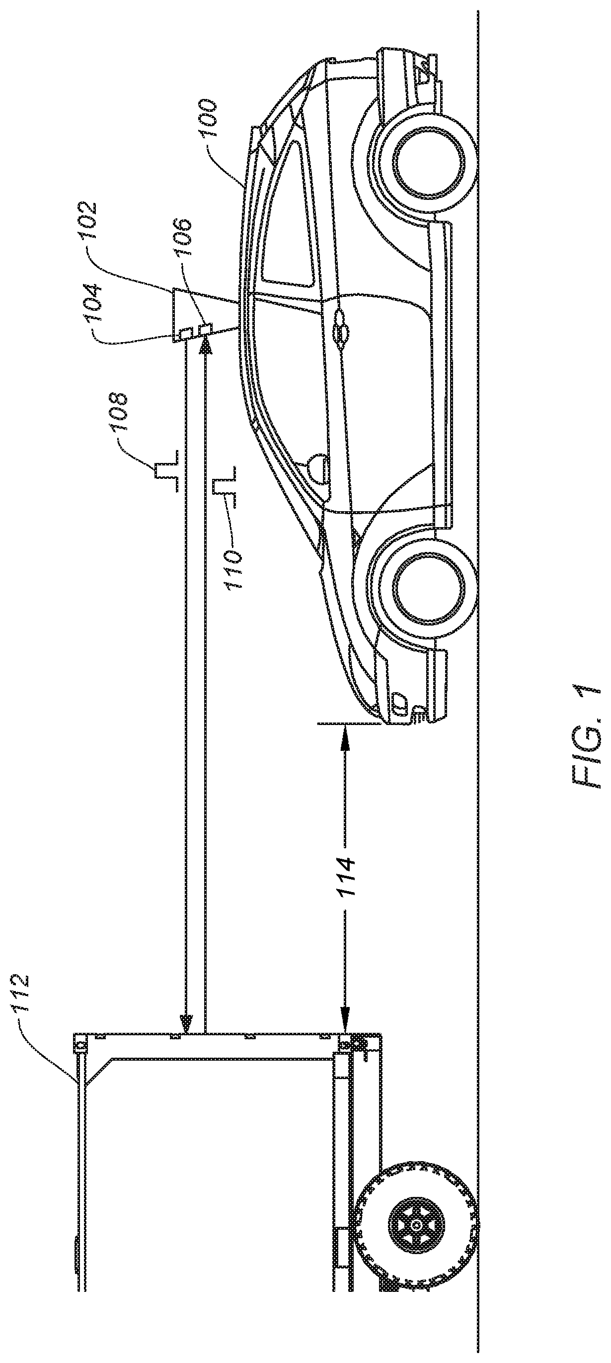
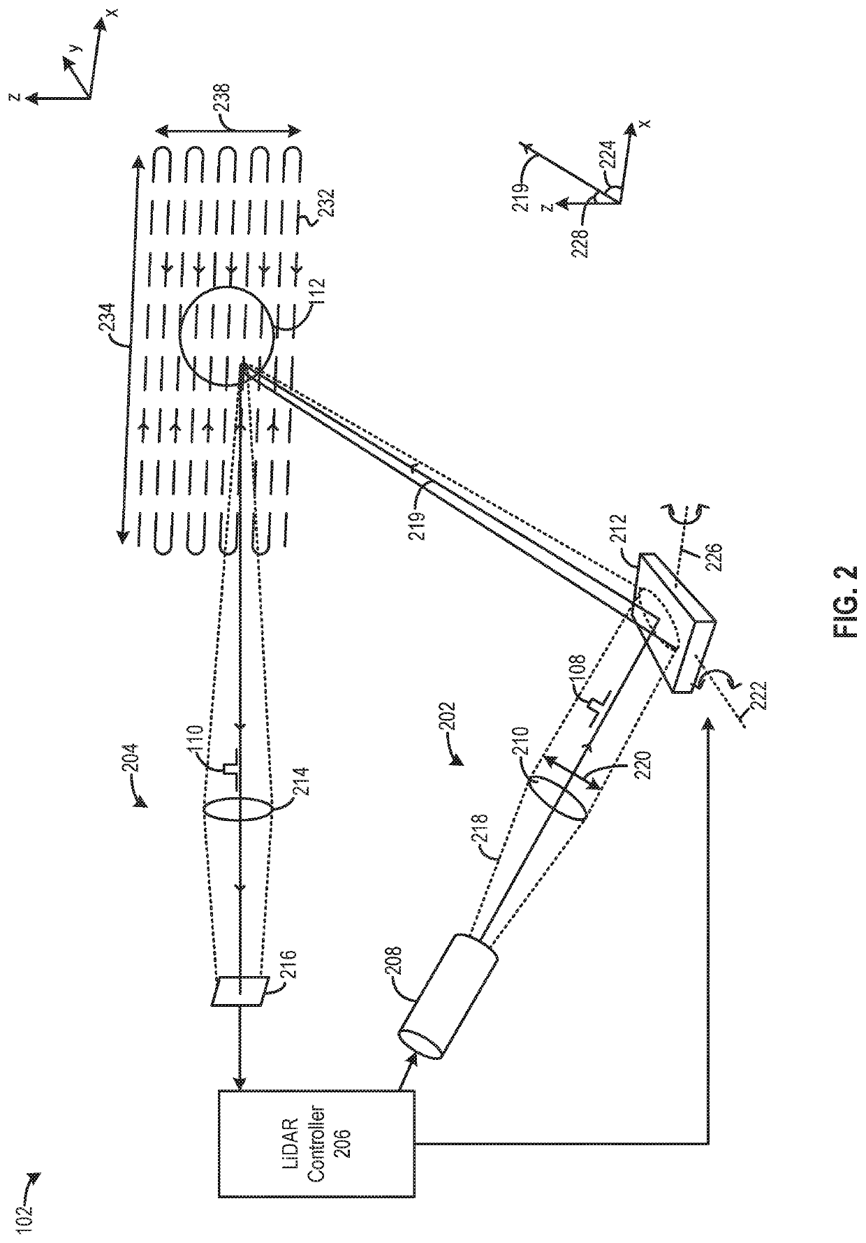
[0034]The following provides a general non-limiting overview of the disclosure that follows. A LiDAR system typically uses a pulsed light source that is focused through a lens assembly to transmit and receive pulses reflected off o...


PUM


Abstract

Some embodiments include a MEMS apparatus configured to redirect light in a LiDAR system and includes a support frame and a plurality of mirror elements disposed in a linear array within the support frame including a first mirror element and a second mirror element. Each of the plurality of mirror elements can be rotatable on a rotational axis that is perpendicular to a line defined by the linear array of the plurality of mirror elements and bisects the corresponding mirror element into a first portion and a second portion. The apparatus can include a coupling element having a distal end physically coupled to a first portion of the first mirror element and a proximal end physically coupled to a second portion of the second mirror element such that a rotation of the first mirror element causes a synchronous and equal rotation of the second mirror element.

Description

CROSS-REFERENCES TO RELATED APPLICATIONS[0001]The following eight U.S. patent applications listed below (which includes the present application) are being filed concurrently, and the entire disclosures of the other applications are incorporated by reference into this application for all purposes:[0002]application Ser. No. ______, filed Dec. 7, 2018, entitled “MULTI-THRESHOLD LIDAR DETECTION” (Attorney Docket No. 103343-1103454-000400US);[0003]application Ser. No. ______, filed Dec. 7, 2018, entitled “MIRROR ASSEMBLY FOR LIGHT STEERING” (Attorney Docket No. 103343-1103456-000500US);[0004]application Ser. No. ______, filed Dec. 7, 2018, entitled “COUPLED AND SYNCHRONOUS MIRROR ELEMENTS IN A LIDAR-BASED MICRO-MIRROR ARRAY” (Attorney Docket No. 103343-1103457-000600US);[0005]application Ser. No. ______, filed Dec. 7, 2018, entitled “COUPLED AND SYNCHRONOUS MIRROR ELEMENTS IN A LIDAR-BASED MICRO-MIRROR ARRAY” (Attorney Docket No. 103343-1117781-000610US);[0006]application Ser. No. ______...

Claims


Application Information

Patent Timeline
IPC IPC(8): G02B26/08G02B26/10G02B27/09G01S7/481G01S17/93G01S17/10
CPCG01S17/10G02B27/0977G02B26/101G02B26/0833G02B27/0955G01S7/4815G01S17/931G01S7/4817
Inventor ZHOU, QINWANG, YOUMIN
Owner BEIJING VOYAGER TECH CO LTD
Why Eureka
Try Eureka