Liquid discharge apparatus

a liquid discharge apparatus and liquid discharge technology, which is applied in the direction of printing, other printing apparatus, etc., can solve the problems of liquid not being normally liquid being discharged from the nozzle in some cases, and viscosity of liquid being affected,

Active Publication Date: 2016-06-30
BROTHER KOGYO KK
View PDF1 Cites 7 Cited by
  • Summary
  • Abstract
  • Description
  • Claims
  • Application Information

AI Technical Summary

Benefits of technology

[0010]For example, when the discharge failure is caused by the thickening of liquid which has not proceeded so much, simply vibrating the meniscus in the nozzle without discharging liquid agitates the liquid in the nozzle, thereby making it possible to eliminate the thickening of liquid. Further, even when the thickening of liquid has proceeded to some degree, the thickening of liquid can be eliminated by the flushing in which a relatively small amount of liquid is discharged from the nozzle. Thus, if the purge discharging a large amount of liquid is performed to eliminate such a discharge failure, it is a waste of liquid and thus uneconomical. On the other hand, when the discharge failure is caused by mixing of bubbles and / or foreign substances in the liquid channel, the purge is effective. In the purge, a large amount of liquid is discharged from nozzles in a short time so as to discharge mixed bubbles and foreign substances together with the liquid. Since the meniscus vibration and flushing are not likely to eliminate the discharge failure caused by mixing of bubbles and / or foreign substances, performing these less effective operations results in a waste of time. Further, the flushing results in a waste of liquid.
[0012]An object of the present teaching is to effectively eliminate the discharge failure of a nozzle which has been detected by meniscus vibration, by performing a recovery operation suitable for the cause of the discharge failure.
[0024]In the present teaching, the driving unit applies at least one meniscus driving signal, of the meniscus driving signals, to the driving element. When a nozzle has discharge failure due to a certain cause, the driving unit may apply a meniscus driving signal, of the meniscus driving signals, which corresponds to the cause of the discharge failure. In this case, the meniscus vibrates greatly and the light receiving amount received by the light receiving part changes greatly. Thus, the cause of the discharge failure can be determined on the basis of the meniscus driving signal used and the change in the light receiving amount, and thereby making it possible to perform the recovery operation suitable for the cause of the discharge failure.

Problems solved by technology

Liquid discharge apparatuses discharging liquid from nozzles have discharge failure in some cases.
The causes of the discharge failure include, for example, the increase in viscosity of liquid in the nozzle which results from dryness (hereinafter referred to as “thickening of liquid”) and mixing of bubbles in a liquid channel.
The discharge failure causes such a situation that the liquid is not normally discharged from the nozzle.
Thus, a part of the light introduced into the waveguide leaks in the nozzle, thereby reducing an amount of light received by the light receiving part.
In addition to the thickening of liquid and the mixing of bubbles in the nozzle, various factors including, for example, mixing of foreign substances into a liquid channel including the nozzle and deterioration of an actuator element may cause the discharge failure of the nozzle.
Thus, if the purge discharging a large amount of liquid is performed to eliminate such a discharge failure, it is a waste of liquid and thus uneconomical.
Since the meniscus vibration and flushing are not likely to eliminate the discharge failure caused by mixing of bubbles and / or foreign substances, performing these less effective operations results in a waste of time.
Further, the flushing results in a waste of liquid.
This results in the differences in the travelling direction of light passing through the meniscus, the travelling direction of light reflected by the meniscus, and the light amount received by the light receiving part between the nozzle having discharge failure and the nozzle having no discharge failure.

Method used


Image

  • Liquid discharge apparatus
  • Liquid discharge apparatus
  • Liquid discharge apparatus

Examples


Embodiment Construction

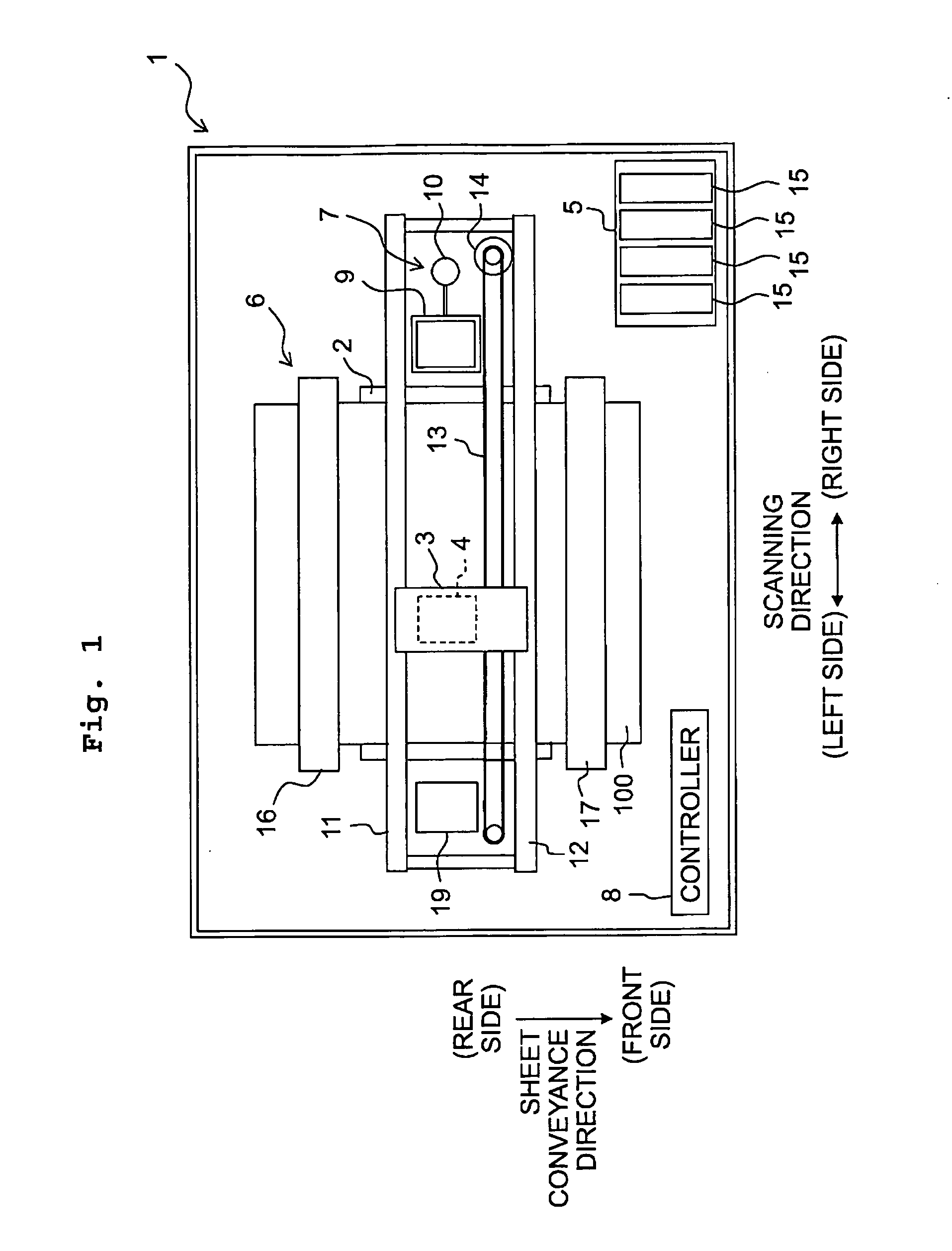
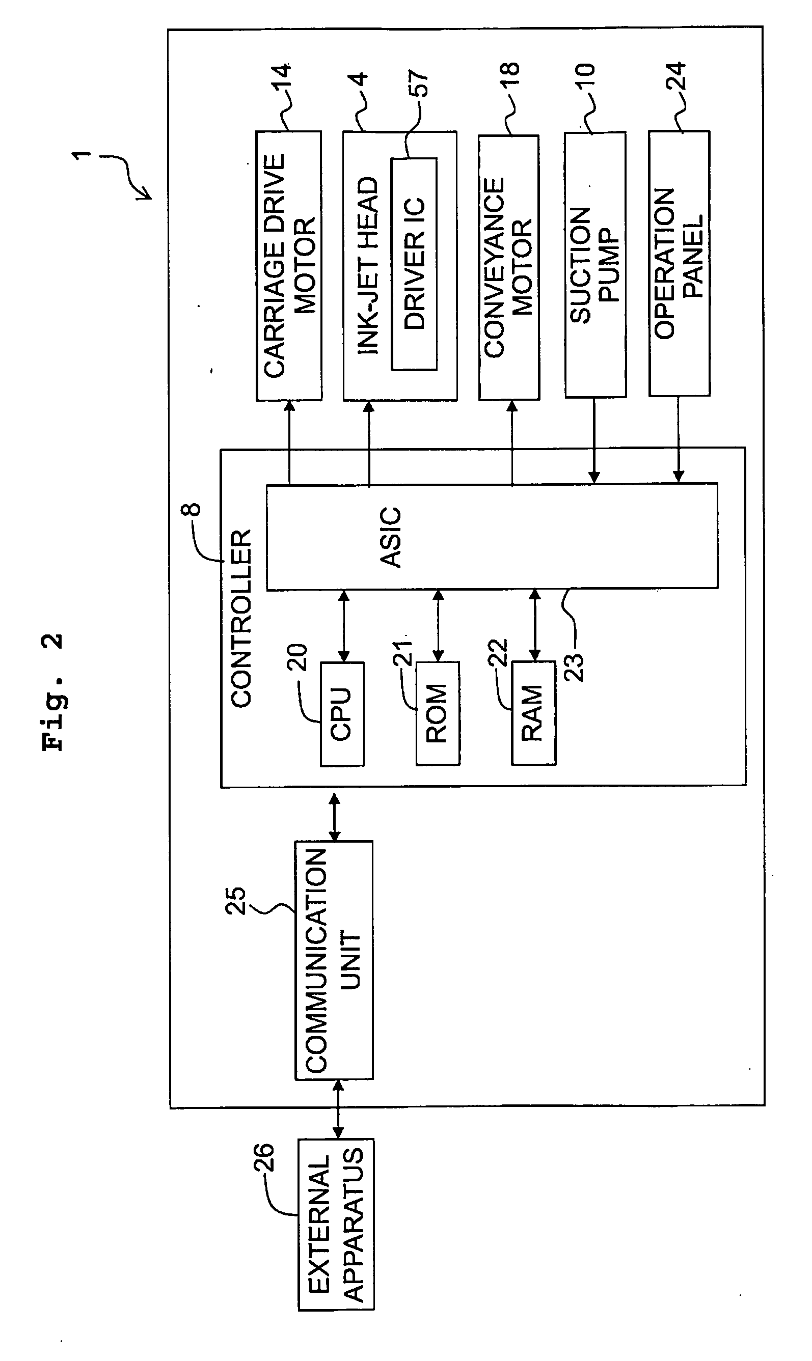
[0042]Subsequently, an explanation will be made about an embodiment of the present teaching. A scanning direction indicated in FIG. 1 is defined as a left-right direction of a printer 1. The upstream side in a sheet conveyance direction in FIG. 1 is defined as the rear side of the printer 1 and the downstream side in the sheet conveyance direction is defined as the front side of the printer 1. A direction perpendicular to the scanning direction and the sheet conveyance direction (direction perpendicular to the paper surface of FIG. 1) is defined as an up-down direction of the printer 1. Noted that the upper paper surface of FIG. 1 (the surface on which FIG. 1 is depicted) is defined as the upper side of the printer 1 and the back surface of FIG. 1 is defined as the lower side of the printer 1.

[0043]

[0044]As depicted in FIGS. 1 and 2, the ink jet printer 1 includes a platen 2, a carriage 3, an ink jet head 4, a cartridge holder 5, a conveyance mechanism 6, a maintenance unit 7, a con...


PUM


Abstract

There is provided a liquid discharge apparatus including: a liquid discharge head which includes a channel structure provided with a nozzle and a liquid channel, a driving element, and a driving unit; a light emitting part; a liquid receiving part receiving light passed through or reflected by the meniscus; and a controller. The controller controls the driving unit to apply at least one of several kinds of meniscus driving signals to the driving element in a state that the light emitting part emits the light to the nozzle, thereby vibrating the meniscus in the nozzle, and is configured to determine a recovery operation from among several kinds of recovery operations which have mutually different liquid discharge amounts to be discharged from the nozzle, on the basis of an amount of light which is received by the light receiving part in the case of vibrating the meniscus of the liquid.

Description

CROSS REFERENCE TO RELATED APPLICATION[0001]The present application claims priority from Japanese Patent Application No. 2014-265266 filed on Dec. 26, 2014, the disclosure of which is incorporated herein by reference in its entirety.BACKGROUND[0002]1. Field of the Invention[0003]The present invention relates to a liquid discharge apparatus configured to discharge liquid.[0004]2. Description of the Related Art[0005]Liquid discharge apparatuses discharging liquid from nozzles have discharge failure in some cases. The causes of the discharge failure include, for example, the increase in viscosity of liquid in the nozzle which results from dryness (hereinafter referred to as “thickening of liquid”) and mixing of bubbles in a liquid channel. The discharge failure causes such a situation that the liquid is not normally discharged from the nozzle. There have been conventionally known various technologies for inspecting discharge failure of the nozzle, such as the technology for inspecting ...

Claims


Application Information

Patent Timeline
Patent Type & Authority Applications(United States)
IPC IPC(8): B41J2/045
CPCB41J2/04581B41J2/04596B41J2/16517B41J2002/16573B41J2/16579B41J2/0451B41J2/0456B41J2/04561B41J2002/1657
Inventor HASEGAWA, SHIN
Owner BROTHER KOGYO KK
Why Eureka
Try Eureka