Side-illuminated excitation optics apparatus and systems

an excitation optics and apparatus technology, applied in the field of apparatus and systems associated with solid state illumination, can solve the problems that additional components add cost and complexity, and the light cannot be achieved by simply reflecting the excitation spectrum, and achieve the effect of better spatial distribution of energy conten

Active Publication Date: 2016-06-30
TEXAS INSTR INC
View PDF2 Cites 20 Cited by
  • Summary
  • Abstract
  • Description
  • Claims
  • Application Information

AI Technical Summary

Benefits of technology

[0021]Some area(s) of the emitting surface are coated with one or more types of phosphor, each designed to fluoresce in a particular narrow band spectrum of light (“fluoresced spectrum”) when excited by the excitation beam. Phosphor coated surfaces of the optical wavelength conversion element thus effectively convert light energy of the excitation spectrum to light energy of the fluoresced spectrum. Some embodiments herein may include switchable Bragg filters to filter unconverted light of the excitation spectrum from the fluoresced output beam. Some embodiments include areas of the emitting surface reflective to light of the excitation spectrum. The reflective areas serve the purpose of including a color of light of the excitation spectrum in the sequence of output beams. The reflective areas may be coated or etched with a dispersive surface to scatter the reflected light and to thus better spatially distribute the energy content of the reflected excitation beam.

Problems solved by technology

One problem with using a dichroic mirror to separate light of the excitation spectrum from light of the fluoresced spectrum is that it may be desirable to include light of a color corresponding to the excitation spectrum (e.g., blue) at the output 165.
The latter cannot be accomplished by simply reflecting light of the excitation spectrum from the phosphor wheel surface, because the dichroic mirror is designed to reflect and not pass light of the excitation spectrum.
Such additional components add cost and complexity.

Method used


Image

  • Side-illuminated excitation optics apparatus and systems
  • Side-illuminated excitation optics apparatus and systems
  • Side-illuminated excitation optics apparatus and systems

Examples


Embodiment Construction

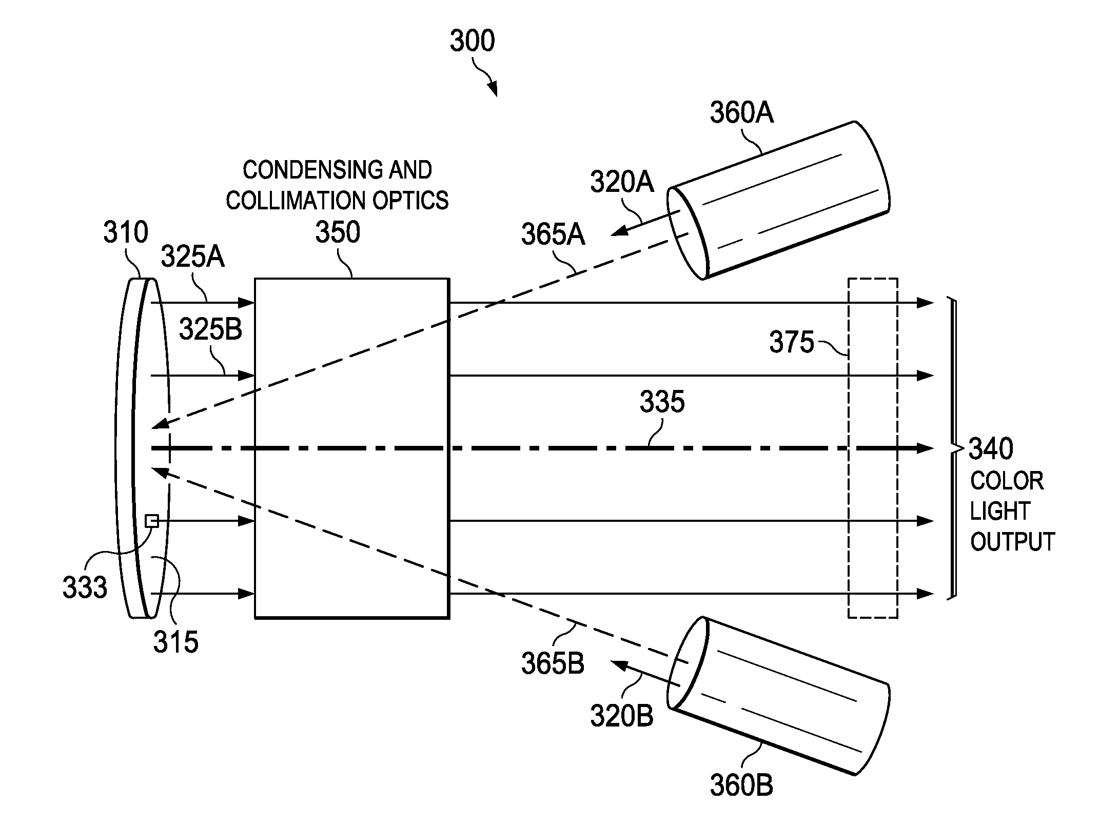
[0024]FIG. 3 is a schematic diagram of a low etendue, narrow band excitation light source illumination apparatus 300 according to various embodiments of the invention. The illumination apparatus 300 includes an optical wavelength conversion element 310. The wavelength conversion element 310 may of any shape and may be capable of rotation or may be designed to be stationary. In some embodiments, the optical wavelength conversion element 310 of the apparatus 300 may be a wheel capable of spinning as further described below. One or more portions of an emitting surface 315 of the wavelength conversion element 310 is coated with a fluorescent phosphor. Two or more portions of the surface 315 may be coated with different phosphors, each designed to fluoresce in a different narrow band spectrum when illuminated with an excitation beam of light of an excitation spectrum. For example, the phosphors may be designed to fluoresce in spectra corresponding to two or more of the primary colors red...


PUM

PropertyMeasurementUnit
excitation spectrumaaaaaaaaaa
angular velocityaaaaaaaaaa
lengthaaaaaaaaaa

Abstract

One or more excitation energy sources emit light in an excitation spectrum and direct the emitted light as an excitation beam to the emitting surface of a wavelength conversion element directly or via reflection. Distinct areas of the emitting surface are coated with one or more distinct fluorescent phosphors. The phosphor-coated areas receive the excitation beam and generate a sequence of fluoresced light beams at a light output, each fluoresced beam of a narrow spectrum determined by the type of phosphor and the excitation spectrum. The fluoresced beams travel parallel to an emitting axis at a non-zero angle to axes associated with the excitation beams.

Description

TECHNICAL FIELD[0001]Embodiments described herein relate to apparatus and systems associated with solid state illumination, including illumination associated with image projection.BACKGROUND INFORMATION[0002]For modern systems of illumination, whether illumination associated with ambient lighting, image capture, image projection, image viewing, signage illumination and / or projection, etc. it is often desirable to generate light with one or more narrow band spectral components. In particular, it is often desirable to generate narrow band spectra corresponding to one or more of the additive primary-color components red (“R”), green (“G”) and blue (“B”) and / or spectra corresponding to one or more of the subtractive color components magenta (“M”), cyan (“C”) and yellow (“Y”). A full set of narrow band spectra corresponding to the primary colors may be color-balanced to create white light. White light may in turn be filtered to create any other color.[0003]Another example use of a set of...

Claims


Application Information

Patent Timeline
Patent Type & Authority Applications(United States)
IPC IPC(8): G02B26/08F21V14/08G02B26/00G02F1/29G02B5/18G02B27/09F21V13/08F21V9/10F21V14/04F21V9/40
CPCG02B26/0833F21V9/10F21V14/08G02B26/008G02F1/292G02B5/1861G02B27/0927F21V13/08F21V14/04H04N9/3158F21V3/12H04N13/257H04N13/324H04N13/398F21V7/28G03B21/2033H04N9/3111H04N9/3161G02B6/0016H04N9/315G09G5/026G09G2300/0452G09G3/3607H04N9/3155H04N9/3182G09G3/3406G02B2207/113G09G3/2003G09G2320/0646G09G3/3413H04N9/3152G03B21/008G03B21/204G09G3/3433H04N9/3129H04N5/7458H04N9/3164G03B21/28H04N2005/7483G03B33/06H04N9/67H04N9/31G02B5/1842G02B30/24H04N23/00H04N23/10H04N23/88H04N25/745
Inventor BHAKTA, VIKRANT R.DAVIS, MICHAEL T.
Owner TEXAS INSTR INC
Why Eureka
Try Eureka