
Swirler, steam separator including the swirler, and nuclear boiling water reactor including the same

a technology of steam separator and swirler, which is applied in the direction of separation process, nuclear elements, greenhouse gas reduction, etc., can solve the problems of increasing the radioactivity level of the plant, adversely affecting outage performance, and increasing the moisture carry-over

Active Publication Date: 2016-06-30
GE HITACHI NUCLEAR ENERGY AMERICAS
View PDF7 Cites 5 Cited by
  • Summary
  • Abstract
  • Description
  • Claims
  • Application Information

AI Technical Summary

Benefits of technology

The patent text describes a steam separator used in a nuclear boiling water reactor. The steam separator includes a standpipe and a swirler with vanes that separate gas-liquid two-phase flow. The swirler has a direct flow channel and an indirect flow channel, with the vanes dividing the space between them. The vanes have lateral surfaces that define the indirect flow channels. The swirler can also have an inner housing that defines the direct flow channel. The technical effect of the invention is to improve the separation of gas-liquid two-phase flow in a nuclear boiling water reactor.

Problems solved by technology

Therefore, if the two-phase flow stream (FS) velocity is high and / or steam separator inlet moisture content is high, the number of the minute droplets that are carried by the steam is increased, which may result in an increase in moisture carry-over.
The increase in moisture carry-over increases the radioactivity levels in the plant and adversely affects outage performance.
If the moisture carry-over levels become undesirably high, certain components of the main steam line and turbine can be adversely impacted as a result of enhanced degradation from such mechanisms such as flow accelerated corrosion leading to higher maintenance costs.

Method used


Image

  • Swirler, steam separator including the swirler, and nuclear boiling water reactor including the same
  • Swirler, steam separator including the swirler, and nuclear boiling water reactor including the same
  • Swirler, steam separator including the swirler, and nuclear boiling water reactor including the same

Examples


Embodiment Construction

[0035]It should be understood that when an element is referred to as being “on,”“connected to,”“coupled to,” or “covering” another element, it may be directly on, connected to, coupled to, or covering the other element or intervening elements that may be present. In contrast, when an element is referred to as being “directly on,”“directly connected to,” or “directly coupled to” another element, there are no intervening elements present. Like numbers refer to like elements throughout the specification. As used herein, the term “and / or” includes any and all combinations of one or more of the associated listed items.

[0036]It should be understood that, although the terms first, second, third, etc. may be used herein to describe various elements, components, regions, layers and / or sections, these elements, components, regions, layers, and / or sections should not be limited by these terms. These terms are only used to distinguish one element, component, region, layer, or section from anoth...


PUM

PropertyMeasurementUnit
volumeaaaaaaaaaa
temperatureaaaaaaaaaa
velocityaaaaaaaaaa

Abstract

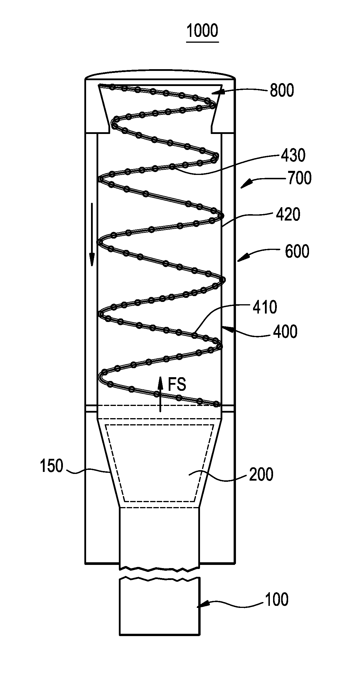
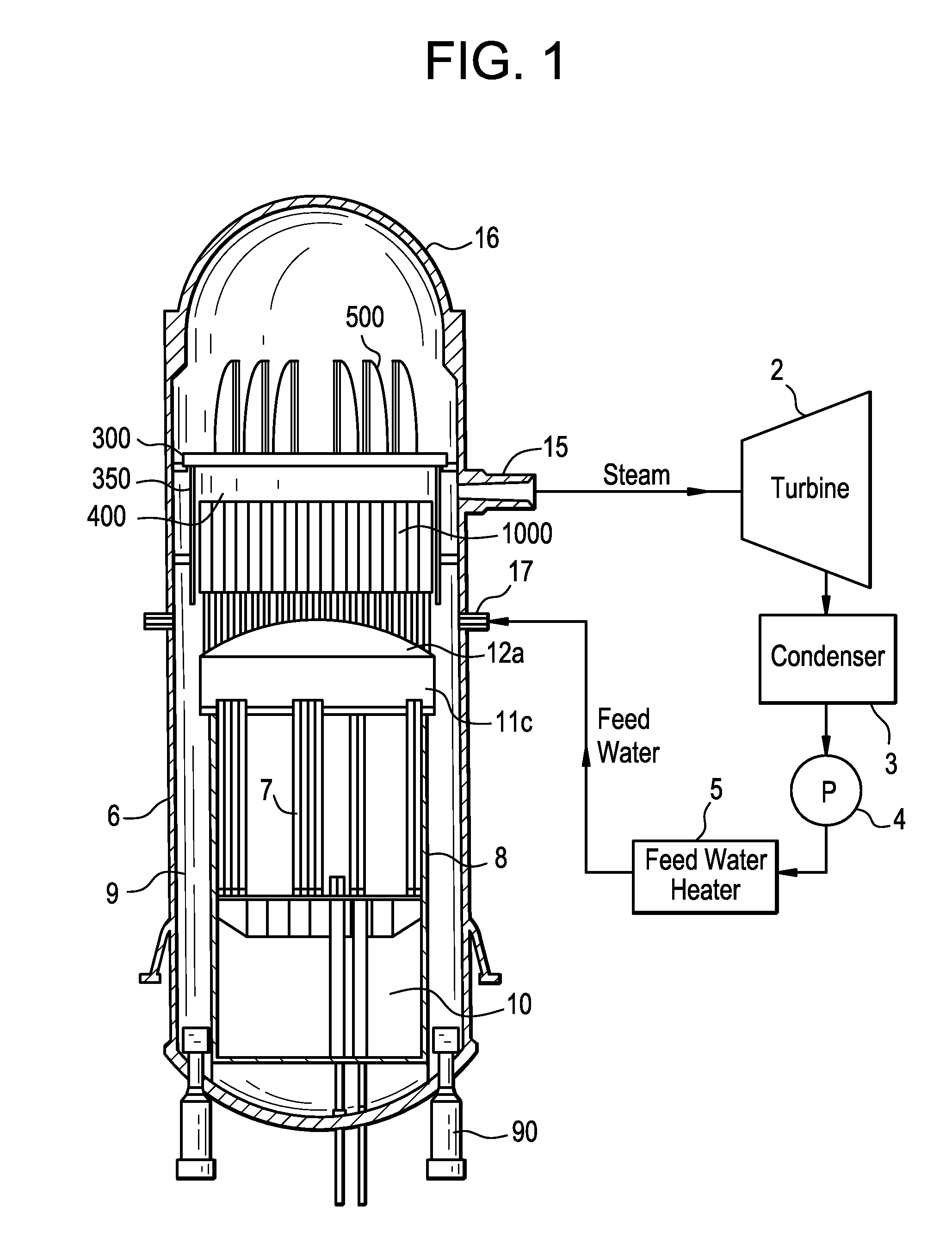
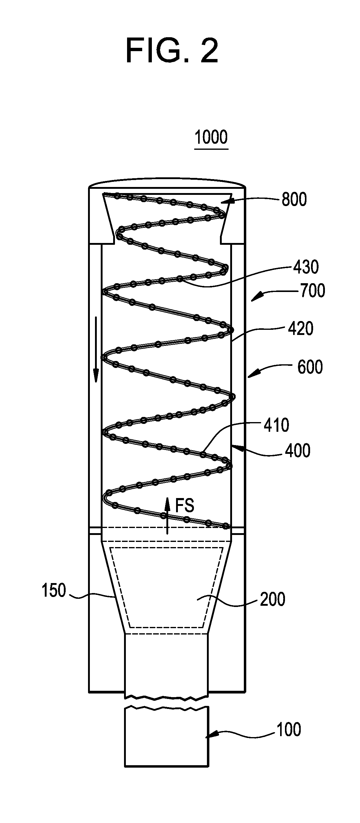
In one embodiment, the steam separator includes a standpipe configured to receive a gas-liquid two-phase flow stream, and a first swirler configured to receive the gas-liquid two-phase flow stream from the standpipe. The first swirler is configured to separate the gas-liquid two-phase flow stream. The first swirler includes a direct flow portion and an indirect flow portion. The direct flow portion has a direct flow channel for permitting direct flow of the gas-liquid two-phase flow stream through the first swirler, and the indirect flow portion has at least one indirect flow channel defined by at least one vane in the first swirler for providing an indirect flow of the gas-liquid two-phase flow stream through the first swirler.

Description

BACKGROUND[0001]1. Field[0002]Example embodiments relate to a swirler, a steam separation system for a nuclear boiling water reactor and / or a nuclear boiling water reactor.[0003]2. Description of Related Art[0004]A boiling water nuclear reactor generates steam by utilizing heat generated from a core and rotates a turbine and a power generator by means of the steam. In a pressurized water nuclear reactor, cooling water separately flows into a primary cooling system circulating through the nuclear reactor, and a secondary cooling system serving as a steam generator. In the primary cooling system, high-temperature water is generated by the heat generated from the nuclear reactor core. In the secondary cooling system, water in the secondary cooling system is boiled in a heat exchanger in the steam generator to become steam, which rotates a turbine or a power generator.[0005]Regardless of the reactor type, moisture must be removed from the steam to be supplied to the turbine. To this end...

Claims


Application Information

Patent Timeline
Patent Type & Authority Applications(United States)
IPC IPC(8): G21C15/16G21D5/12B04C1/00F16T1/34B01D45/16
CPCG21C15/16F16T1/34G21D5/12B04C1/00B01D45/16F22B37/268Y02E30/30F22B37/327F01K5/00
Inventor MISTREANU, ADRIAN M.BOWMAN, JAMES SCOTTELLISON, PHILLIP GLENBENNION, JOHN S.ALPAY, BULENT
Owner GE HITACHI NUCLEAR ENERGY AMERICAS
Learn More