Ergonomic knife attachment

a knife and ergonomic technology, applied in the field of knives, can solve the problems of difficult mastery of the method of gripping a knife, and achieve the effect of improving safety and improving gripping by users

a knife and ergonomic technology, applied in the field of knives, can solve the problems of difficult mastery of the method of gripping a knife, and achieve the effect of improving safety and improving gripping by users

US20160193742A1Inactive Publication Date: 2016-07-07FAIOLA NORMAN

Image

  • Ergonomic knife attachment
  • Ergonomic knife attachment
  • Ergonomic knife attachment

Examples


Embodiment Construction

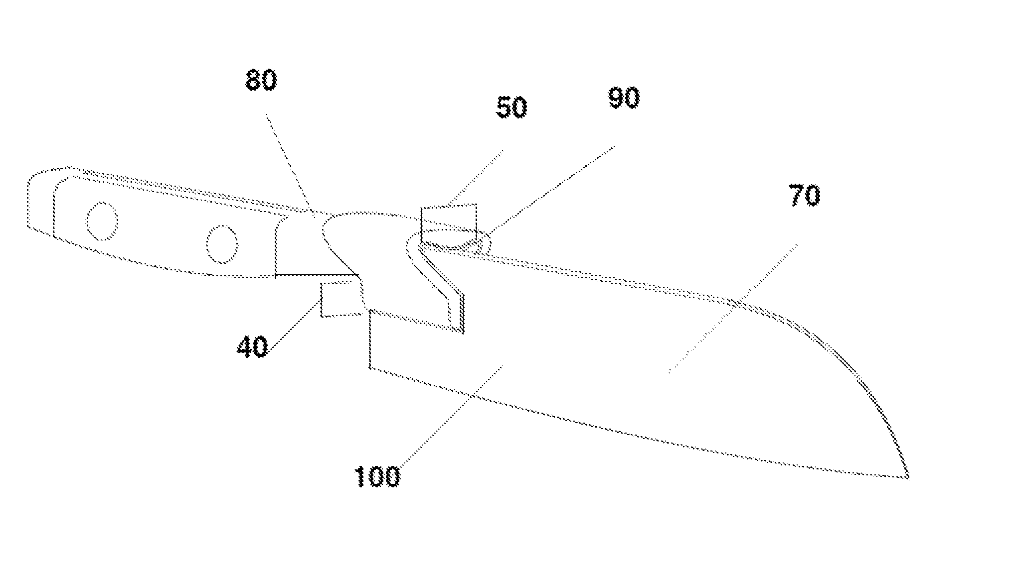
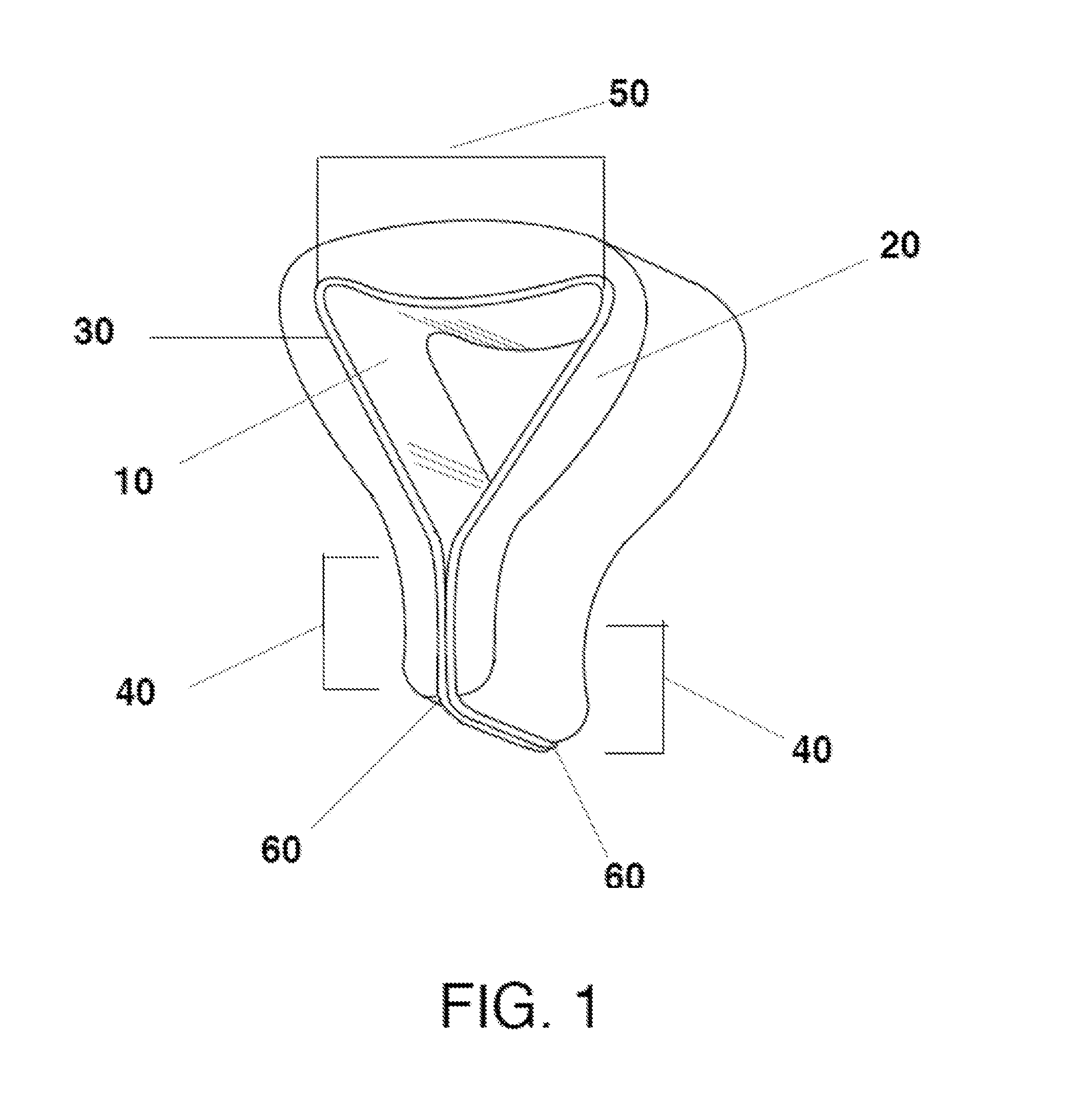
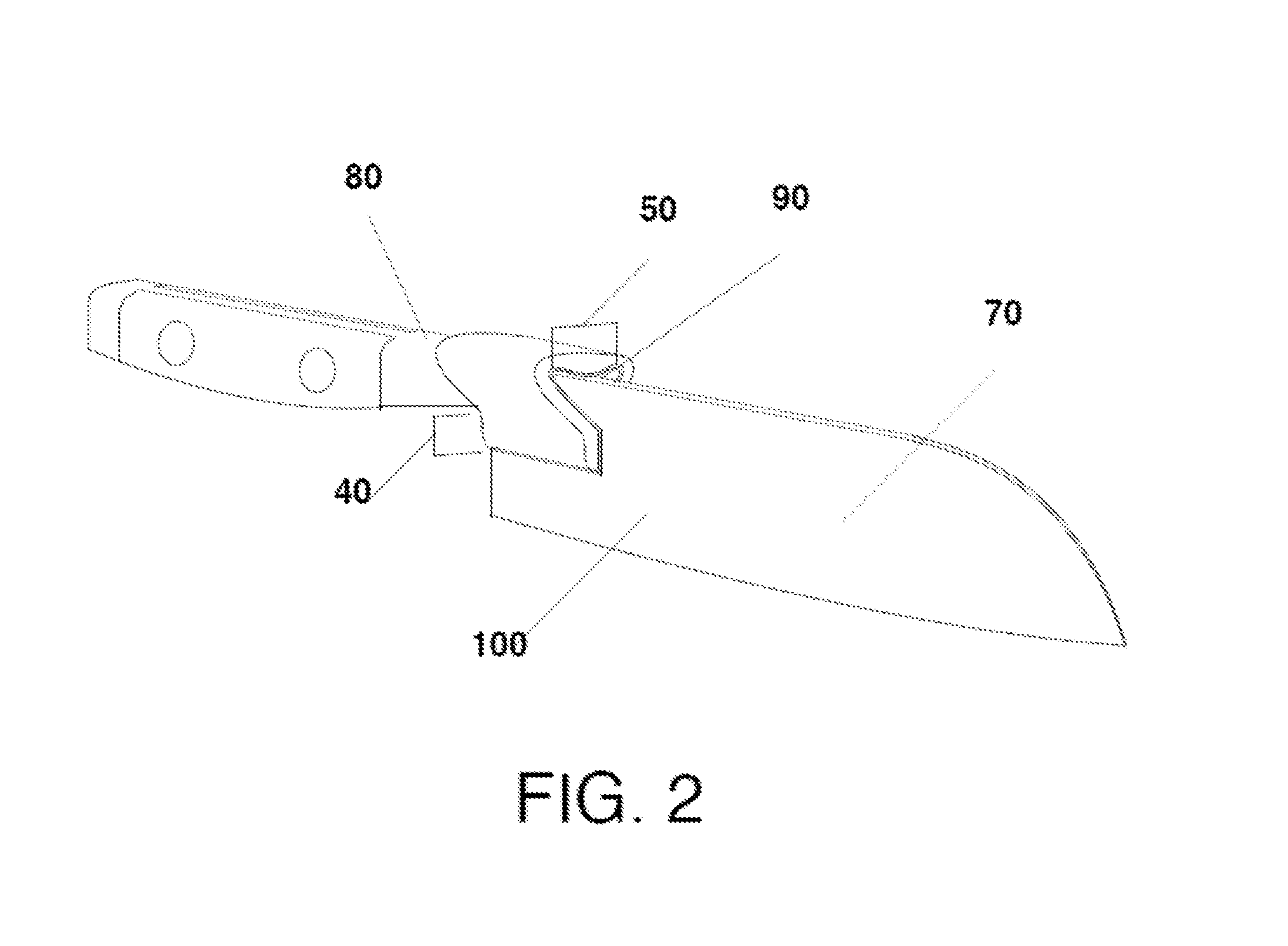
[0013]Referring now to the drawings, wherein like reference numerals refer to like parts throughout, there is seen in FIG. 1 a food-safe, spring-tempered, stainless steel clamping device 10 having a non-toxic silicone or other cushioning layer 20 affixed to the exterior of device 10, such as by a suitable silicone adhesive layer 30. Clamping legs 40 flexibly extend from a central juncture 50 and, due to the geometrical design of the juncture 50, allow clamping legs 40 to forcibly contact each other at their distal ends 60. Device 10 may be made from any spring material, such as metals and plastics, which will allow clamping legs 40 to securely grasp and be held in place on the blade of a knife. For example, stainless steel grades 409, 410, 430, 201, 202, or 304, may be used with grade 304 preferred. Cushioning layer 20 preferably comprises a Generally Regarded As Safe (GRAS) silicone basic polymer as described in ASTM method D1418-81, Standard Practice for Rubber and Rubber Latices—...


PUM

PropertyMeasurementUnit
Angleaaaaaaaaaa
Adhesivityaaaaaaaaaa
Widthaaaaaaaaaa

Abstract

A device that may be attached to the blade of a knife to improve safety. The device has a central juncture and a pair of opposing legs having free ends that extend from the central juncture to define a gap therebetween. The free ends of the opposing legs are held in frictional engagement with each other. The gap is dimensioned to accept the blade of a knife and the central juncture will extends along a plane at right angles to the blade of the knife to accommodate the first phalanx of a human index finger. A cushioning layer is positioned over the central juncture and pair of opposing legs to improve gripping by a user and thus improve safety.

Description

BACKGROUND OF THE INVENTION[0001]1. Field of the Invention[0002]The present invention relates to cutlery and, more specifically, to an attachment for a knife that improves grip and encourages safe use.[0003]2. Description of the Related Art[0004]The proper use of kitchen cutlery involves a user grasping the handle and blade of a knife so that the thumb and index finger actually rest on either side of the blade of a knife with the phalanx of the index finger positioned along the spine of the knife blade. This method of gripping a knife is difficult to master and, when not performed properly, can lead to accidents. Thus, there is a need in the art for a device to assist a user with properly grasping a knife.BRIEF SUMMARY OF THE INVENTION[0005]A device for attachment to the blade of a knife having a central juncture having a predetermined width and a pair of opposing legs having free ends extending from the central juncture to define a gap therebetween, wherein the free ends of the opp...

Claims


Application Information

Patent Timeline
07 Jul 2016
Publication
US20160193742A1
IPC
B26B29/02; B26B3/00
CPC
B26B3/00; B26B29/02
Inventors
FAIOLA, NORMAN