Pneumatic tire

a technology of pneumatic tires and tires, applied in the field of pneumatic tires, can solve the problem of not offering sufficient on-snow performance, and achieve the effect of improving on-snow performan

Active Publication Date:
View PDF11 Cites 9 Cited by
  • Summary
  • Abstract
  • Description
  • Claims
  • Application Information

AI Technical Summary

Benefits of technology

[0006]In view of the above problems in the conventional art, the present invention has an object to provide a pneumatic tire capable of improving on-snow performance.

Problems solved by technology

Unfortunately, the tread block disclosed by the above document may not offer sufficient on-snow performance.

Method used


Image

  • Pneumatic tire
  • Pneumatic tire
  • Pneumatic tire

Examples


example

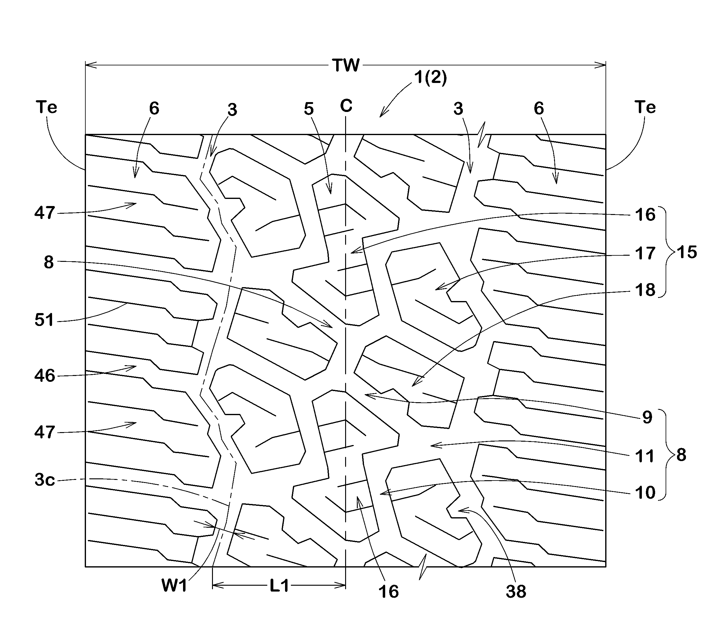
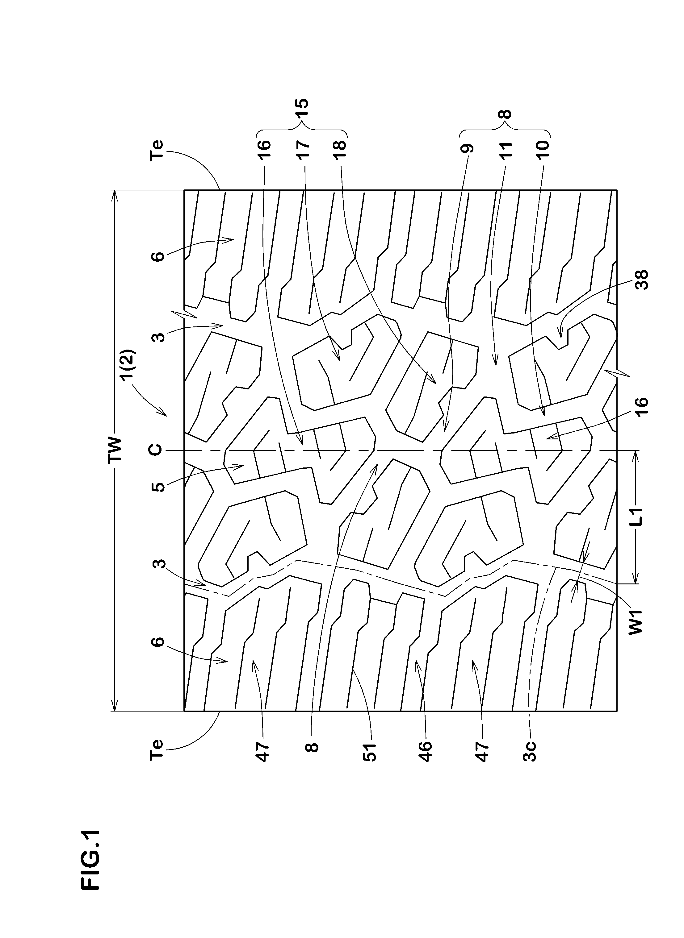
[0069]Pneumatic tires for SUV having a size 265 / 70R17 and a basic pattern illustrated in FIG. 1 were manufactured based on details shown in Table 1. As comparative example, a pneumatic tire with a tread pattern illustrated in FIG. 6, which is not provided with any constricted blocks, was also manufactured. Then, on-snow performance and wear resistance thereof were tested. The common specifications of tires and test procedures are as follows.

[0070]Rim: 17×7.5

[0071]Internal pressure of tires: 220 kPa

[0072]Test vehicle: Four-wheel drive vehicle with displacement of 2400 cc

[0073]Tire location: All wheels

[0074]On-snow performance test:

[0075]On a test course covered with compressed snow, a distance for requiring to accelerate the velocity of the test vehicle from 5 km / h to 20 km / h was measured using GPS.

[0076]Test results are indicated using an index Ref. 1 being 100. The smaller the value, the better the on-snow performance is.

Wear Resistance Test:

[0077]The amount of wear of the tread po...


PUM


Abstract

A pneumatic tire includes a tread portion including a plurality of tread blocks including at least one constricted block with a first recess disposed on axially one side of the block and a second recess disposed on axially other side of the block so as to form a narrow portion between the first recess and the second recess. Each of the first recess and the second recess includes a V-shaped top edge on a ground contacting surface of the block. Each of the V-shaped top edges protrudes toward a center of the block in a planar view of the block.

Description

BACKGROUND OF THE INVENTION[0001]1. Field of the Invention[0002]The present invention relates to pneumatic tires, and in particular, relates to a pneumatic tire capable of improving on-snow performance.[0003]2. Description of the Related Art[0004]Conventionally, pneumatic tires including a tread portion with a plurality of blocks separated by grooves have been proposed. For example, Japanese Unexamined Patent Application Publication No. 2012-066790 discloses a pneumatic tire including a tread block including recessed sidewalls.[0005]Unfortunately, the tread block disclosed by the above document may not offer sufficient on-snow performance.SUMMARY OF THE INVENTION[0006]In view of the above problems in the conventional art, the present invention has an object to provide a pneumatic tire capable of improving on-snow performance.[0007]According to one aspect of the present invention, a pneumatic tire includes a tread portion including a plurality of tread blocks including at least one c...

Claims


Application Information

Patent Timeline
Patent Type & Authority Applications(United States)
IPC IPC(8): B60C11/03B60C11/13
CPCB60C11/0309B60C2011/133B60C11/1307B60C11/0332B60C11/0302B60C2011/0339B60C2011/1209B60C2011/1213B60C11/11B60C11/0306
Inventor NAKAYAMA, HIROYUKI
Why Eureka
Try Eureka