Fire Control Housing

a technology for controlling systems and fire, applied in the direction of firing/trigger mechanisms, weapons, training adaptation, etc., can solve the problem of costly development of a trigger feel

Inactive Publication Date: 2016-07-21
IN OVATION LLC
View PDF2 Cites 3 Cited by
  • Summary
  • Abstract
  • Description
  • Claims
  • Application Information

AI Technical Summary

Benefits of technology

[0008]In some embodiments, a fire control housing comprises a frame defining a cavity. The frame comprises a floor, a first sidewall and an opposed second sidewall

Problems solved by technology

Competent shooters become familiar with the feel of their trigger, which can result after firing the firearm many times. D

Method used


Image

  • Fire Control Housing
  • Fire Control Housing
  • Fire Control Housing

Examples


Embodiment Construction

[0016]While this invention may be embodied in many different forms, there are described in detail herein specific embodiments of the invention. This description is an exemplification of the principles of the invention and is not intended to limit the invention to the particular embodiments illustrated.

[0017]For the purposes of this disclosure, like reference numerals in the figures shall refer to like features unless otherwise indicated.

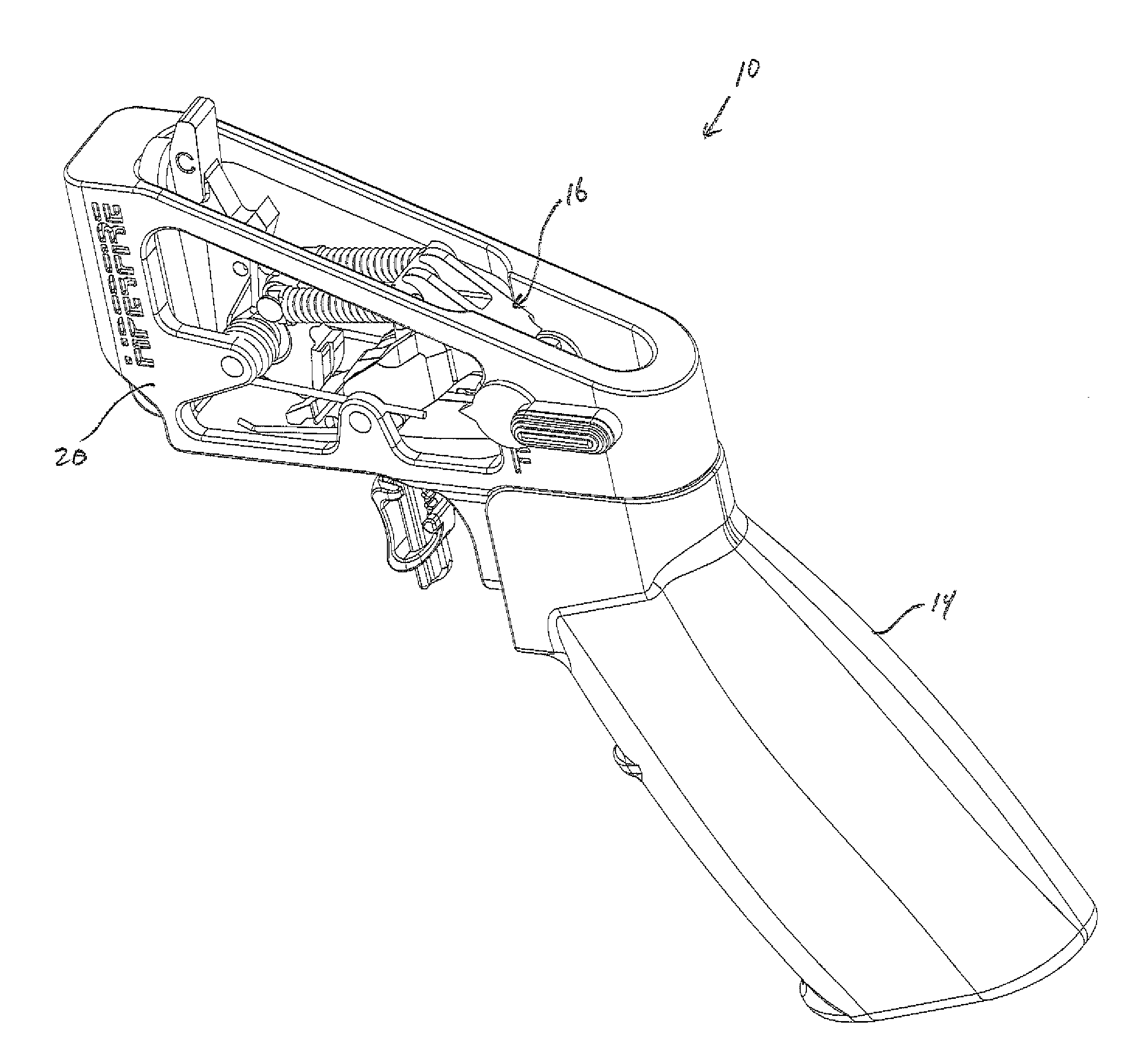
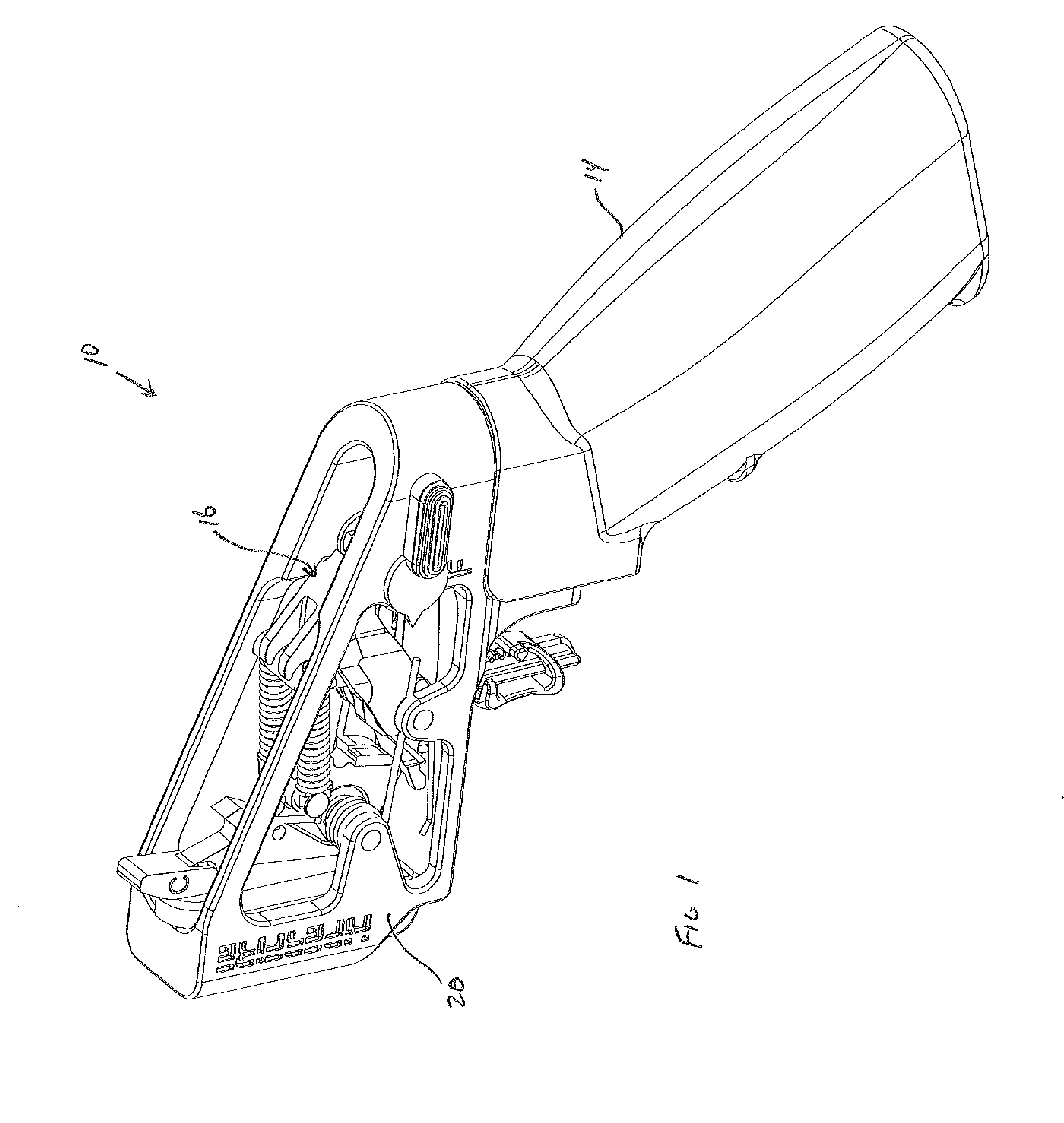
[0018]FIG. 1 shows an embodiment of a trigger housing device 10. In some embodiments, the trigger housing device 10 comprises a frame 20, a trigger group 16 and a grip 14. Desirably, the frame 20 is constructed and arranged to support the trigger group 16. Desirably, the trigger group 16 can be cocked and fired by a user.

[0019]In some embodiments, the trigger housing device 10 provides the structure necessary to support the trigger group 16 and allow the trigger to be cocked and fired, but does not provide other elements that commonly embody a firear...


PUM


Abstract

In some embodiments, a fire control housing comprises a frame defining a cavity. The frame comprises a floor, a first sidewall and an opposed second sidewall. The first sidewall defines a first window. A trigger assembly comprises a hammer and a finger trigger. The finger trigger extends through the floor of the frame.

Description

CROSS-REFERENCE TO RELATED APPLICATIONS[0001]This application claims the benefit of U.S. Patent Application No. 62 / 105,169, filed Jan. 19, 2015, the entire content of which is hereby incorporated herein by reference.BACKGROUND OF THE INVENTION[0002]This invention relates to a housing for a fire control system such as a trigger mechanism for a firearm. In some embodiments, the invention relates to a trigger training device.[0003]Firearms such as the AR-15 are well known in the art. A firearm generally includes a fire control system, such as a trigger group. Different triggers are available for firearms, and the specifics of the trigger can change the performance of the firearm.[0004]Competent shooters become familiar with the feel of their trigger, which can result after firing the firearm many times. Developing a feel for a trigger can be costly, for example requiring trips to a firing range and a good deal of ammunition.[0005]There remains a need for a device capable of displaying ...

Claims


Application Information

Patent Timeline
IPC IPC(8): F41A33/00F41A19/14F41A19/10
CPCF41A33/00F41A19/14F41A19/10
Inventor BENDER, TERRENCE DWIGHT
Owner IN OVATION LLC
Why Eureka
Try Eureka