Recirculating gas system for a manufacturing device.

a manufacturing device and gas system technology, applied in the field of recirculating gas systems for manufacturing devices, can solve the problems of destroying parts, reducing the quality of parts, and causing harm to humans

Inactive Publication Date: 2016-07-28
NORDSTROM JAMES
View PDF1 Cites 63 Cited by
  • Summary
  • Abstract
  • Description
  • Claims
  • Application Information

AI Technical Summary

Benefits of technology

[0010]FIG. 6 is a schematic illustration of the back of the recirculating gas system for a manufacturing device of FIG. 1 that includes one or more gas attribute change devices.

Problems solved by technology

This exposure can be harmful to humans and can reduce the quality of, or ruin a part.

Method used


Image

  • Recirculating gas system for a manufacturing device.
  • Recirculating gas system for a manufacturing device.
  • Recirculating gas system for a manufacturing device.

Examples


Embodiment Construction

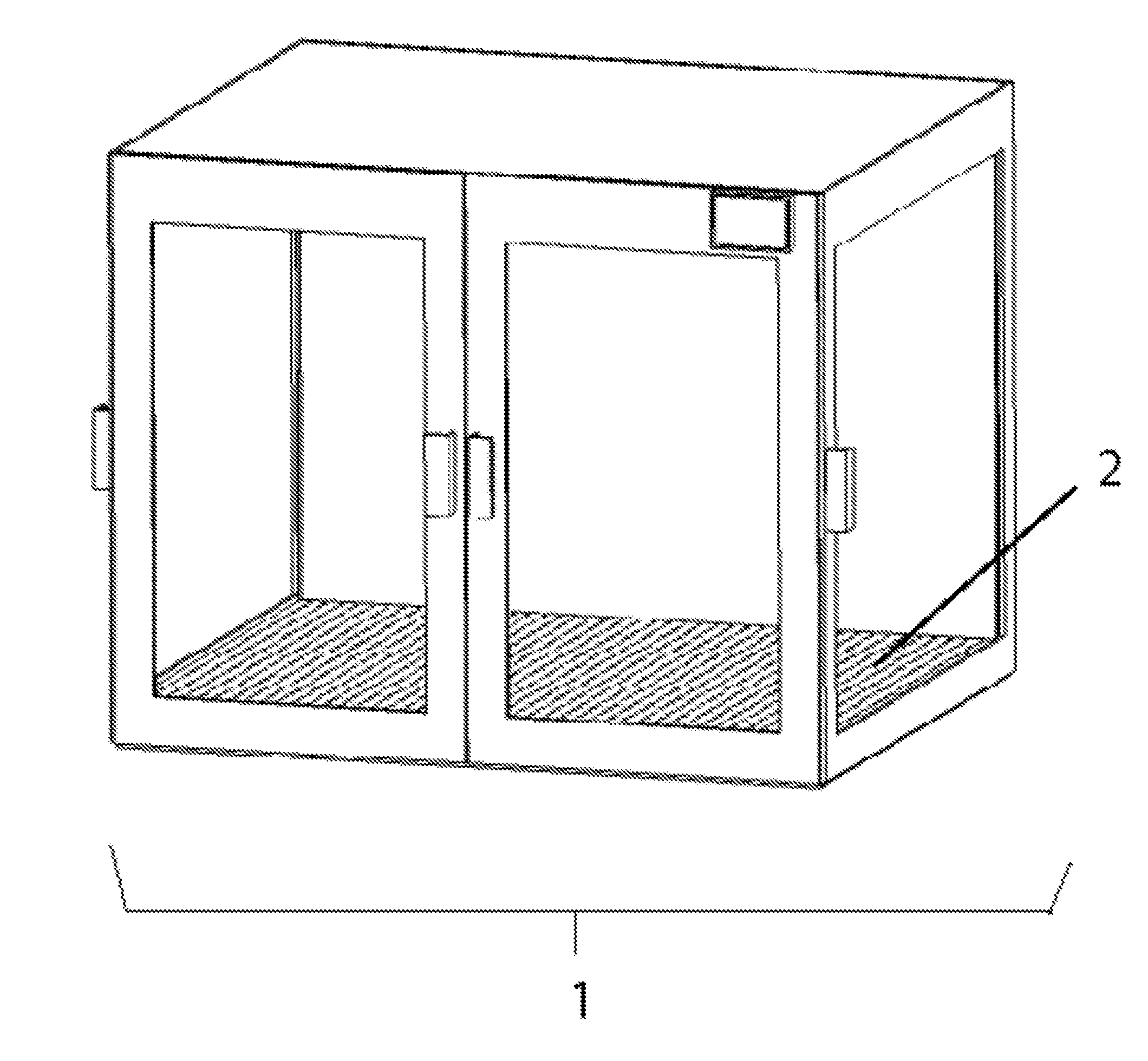
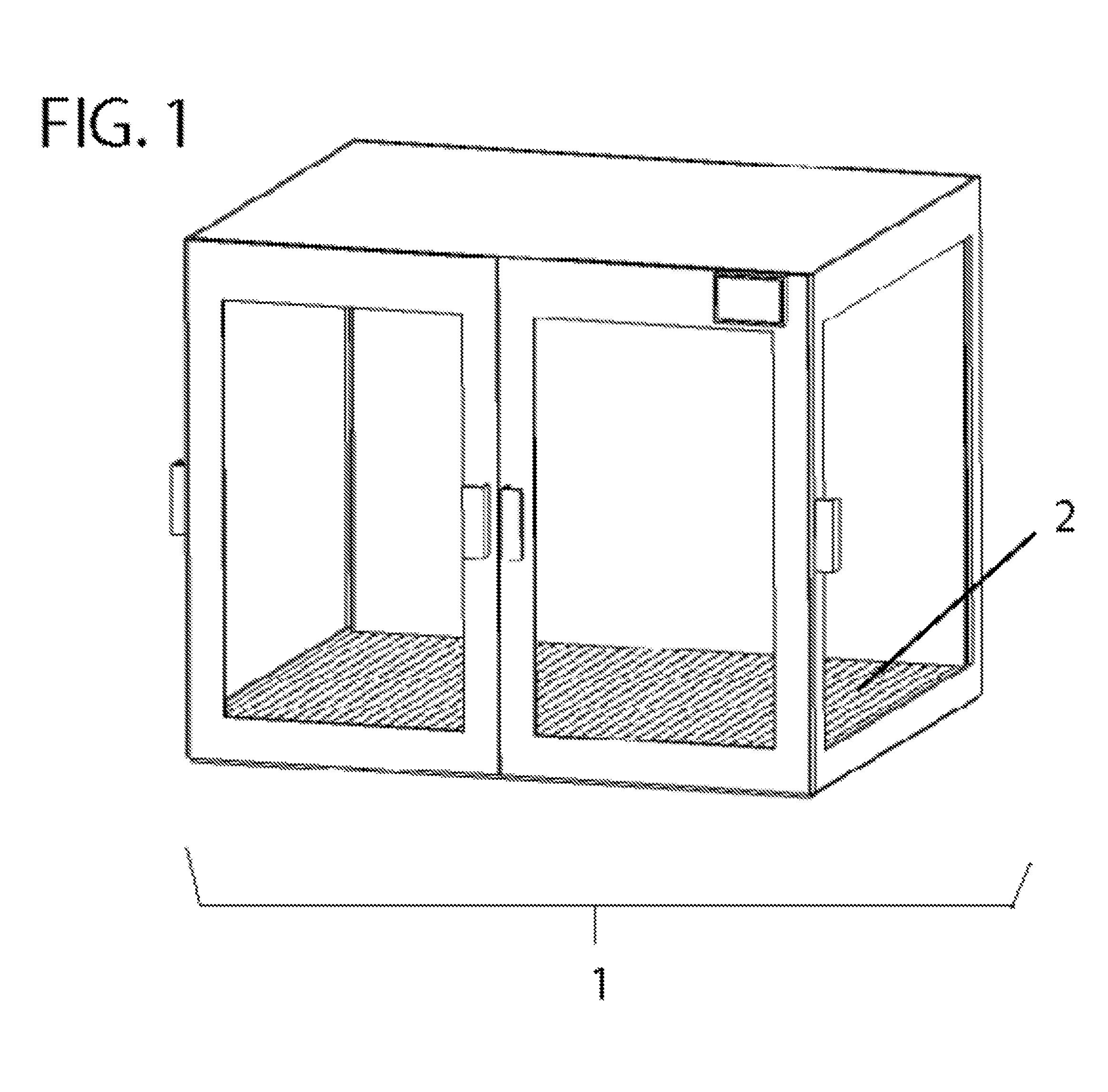
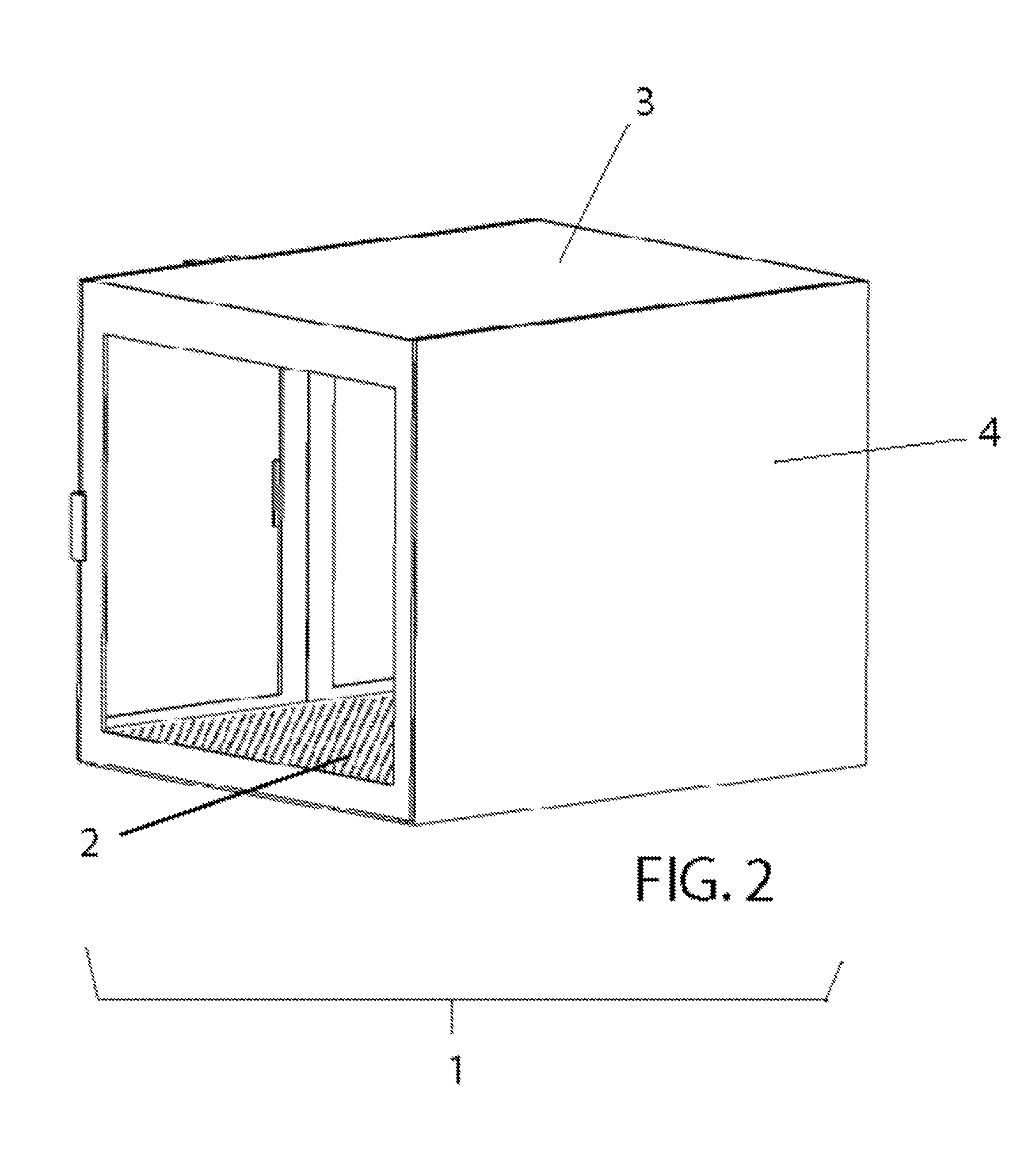
[0011]With reference to the drawings FIGS. 1, 2, 3, 4 and 5 shows the preferred embodiment of a recirculating gas system for a manufacturing device. FIG. 6 shows optional enhancements to the preferred embodiment.

[0012]The recirculating gas system for a manufacturing device of FIGS. 1, 2, 3, 4, 5 and 6 includes an enclosure 1, a gas inlet 8, a gas outlet 12, and an actuator 7 to propel the gas.

[0013]The preferred embodiment optionally uses one or more devices to change the attributes of the recirculating gas. Examples of devices that change the attributes of the recirculating gas are a filter 5, a heater 14, a humidifier 15, a dehumidifier 16 and a cooler 17. Alternative embodiments may change the recirculating gas in any number of industry standard methods.

[0014]The preferred embodiment changes the attributes of the gas by pulling the gas from the perforated bed 2 to the feed bed 10, through the inlet 11, up the rear duct 9, where the gas is optionally exposed to one or more optiona...


PUM

PropertyMeasurementUnit
temperaturesaaaaaaaaaa
humidityaaaaaaaaaa
speedaaaaaaaaaa

Abstract

The present invention is for a recirculating gas system for a manufacturing device. The recirculating gas system consists of an enclosure, a gas inlet, a gas outlet and an actuator to propel the gas.

Description

TECHNICAL FIELD[0001]The present invention relates to a recirculating gas system for a manufacturing device.BACKGROUND OF THE INVENTION[0002]An unenclosed manufacturing device exposes humans to noxious gasses, odors, fumes, ultrafine particles (UFPs), particles, noise and heat, and a part, the item a manufacturing device is creating, to varying temperatures, gas movements and humidity. This exposure can be harmful to humans and can reduce the quality of, or ruin a part.[0003]An enclosed manufacturing device or a enclosure for a manufacturing device with a recirculating gas system can filter noxious gasses, odors, fumes, ultrafine particles (UFPs), particles, noise and heat, and improve the quality of a part by providing consistent temperatures, gas movements and humidity.SUMMARY OF THE INVENTION[0004]The present invention is for a recirculating gas system for a manufacturing device. The recirculating gas system consists of an enclosure, a gas inlet, a gas outlet and an actuator to p...

Claims


Application Information

Patent Timeline
Patent Type & Authority Applications(United States)
IPC IPC(8): B22F3/105B29C67/00
CPCB22F3/1055B29C67/0096B33Y40/00B33Y30/00B22F2003/1059B29C64/35B29C64/364Y02P10/25B22F10/18B22F10/32B22F12/70B22F12/90B22F10/77B22F10/28B22F10/12
Inventor NORDSTROM, JAMES
Owner NORDSTROM JAMES
Why Eureka
Try Eureka